
Electric heating energy-saving storage unit

A technology of thermal energy storage and memory, applied in the field of boilers, can solve the problems of increasing electricity pressure in peak power consumption areas, waste of electric energy in power plants, and increasing production costs, so as to reduce electricity pressure, prevent heat loss, and reduce production costs Effect

Inactive Publication Date: 2014-02-19
泉州恒灼热力机械科技有限公司
View PDF9 Cites 5 Cited by
  • Summary
  • Abstract
  • Description
  • Claims
  • Application Information

AI Technical Summary

Problems solved by technology

This type of heating device generally uses coal, gas, oil, etc. for heating, which consumes a lot of energy, costs relatively high, and pollutes the environment.
[0004] However, in industrial production, it is generally during the daytime, in the peak area of ​​electricity consumption, and the electricity price in the peak area of ​​electricity consumption is high, which not only increases the production cost, but also increases the pressure of electricity consumption in the peak area of ​​electricity consumption, while it is in the valley area of ​​electricity consumption at night, not only the price of electricity is low, And the electric energy of the power plant is wasted for nothing, so a device that can convert electric energy into heat energy for storage at night when the power consumption is low is in line with national policies and has a bright future

Method used

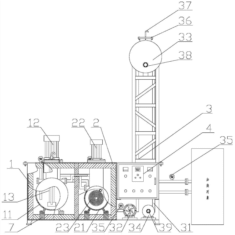
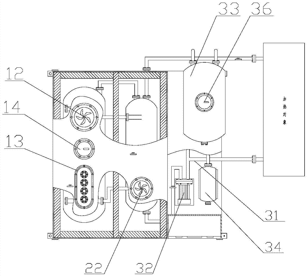
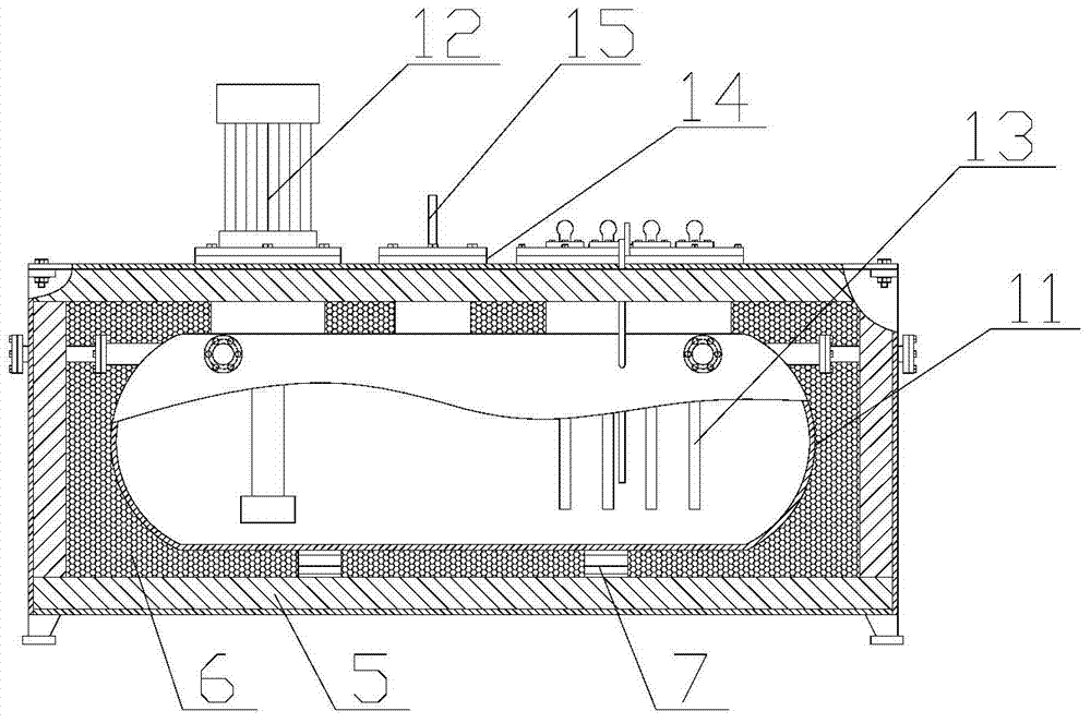

Image

  • Electric heating energy-saving storage unit
  • Electric heating energy-saving storage unit
  • Electric heating energy-saving storage unit

Examples


Embodiment 1

[0031] refer to figure 1 , figure 2 and image 3 , an electric heating energy-saving storage device, including an electric thermal energy storage device 1, a constant temperature heat exchanger 2 and a heat conduction oil heating device 3, and the electric thermal energy storage device 1 is composed of a heat storage tank 11 and an ultra-high temperature pump 12 arranged on the heat storage tank , electric heating wire 13, the heat storage tank 11 is filled with inorganic medium liquid, and the inorganic medium liquid can reach a stable high temperature below 550 degrees when heated under normal pressure. The electric heating wire 13 is installed above the heat storage tank 11 and inserted vertically into the Inside the heat storage tank 11, it is easy to disassemble and assemble, and it is convenient to replace the heating wire. The constant temperature heat exchanger 2 is composed of a constant temperature tank 21, a temperature control pump 22 installed on the constant te...

Embodiment 2

[0041] refer to figure 1 , figure 2 , an electric heating energy-saving storage device, including an electric thermal energy storage device 1, a constant temperature heat exchanger 2 and a heat conduction oil heating device 3, and the electric thermal energy storage device 1 is composed of a heat storage tank 11 and an ultra-high temperature pump 12 arranged on the heat storage tank , electric heating wire 13, the heat storage tank 11 is filled with inorganic medium liquid, and the inorganic medium liquid can reach a stable high temperature below 550 degrees when heated under normal pressure. The electric heating wire 13 is installed above the heat storage tank 11 and inserted vertically into the Inside the heat storage tank 11, it is easy to disassemble and assemble, and it is convenient to replace the heating wire. The constant temperature heat exchanger 2 is composed of a constant temperature tank 21, a temperature control pump 22 installed on the constant temperature tank...

Embodiment 3

[0044] refer to figure 1 , figure 2 , image 3 , Figure 4 , an electric heating energy-saving storage device, including an electric thermal energy storage device 1, a constant temperature heat exchanger 2 and a heat conduction oil heating device 3, and the electric thermal energy storage device 1 is composed of a heat storage tank 11 and an ultra-high temperature pump 12 arranged on the heat storage tank , electric heating wire 13, the heat storage tank 11 is filled with inorganic medium liquid, and the inorganic medium liquid can reach a stable high temperature below 550 degrees when heated under normal pressure. The electric heating wire 13 is installed above the heat storage tank 11 and inserted vertically into the Inside the heat storage tank 11, it is easy to disassemble and assemble, and it is convenient to replace the heating wire. The constant temperature heat exchanger 2 is composed of a constant temperature tank 21, a temperature control pump 22 installed on the ...


PUM


Abstract

The invention discloses an electric heating energy-saving storage unit which is simple in structure, environmentally friendly and energy saving. The electric heating energy-saving storage unit comprises an electric heat storage device, a constant temperature heat exchanger, and a heat transfer oil heating device. The electric heat storage device comprises a heat storage tank, an ultrahigh temperature pump arranged on the heat storage tank, and an electric heating wire. The heat storage tank is filled with organic liquid. The organic liquid can be heated to the high temperature lower than 550 DEG C under the normal pressure. The constant temperature heat exchanger comprises a constant temperature tank, a temperature control pump disposed on the constant temperature tank, and a heat transfer soil heated coil disposed inside the constant temperature tank. The constant temperature tank is communicated with the heat storage tank. The heat transfer oil heating device is connected with a hot oil circulating pump providing cyclic power, an expansion tank and an oil storage tank storing heat transfer oil and heated through a heat transfer oil circulating pipeline. The electric heating energy-saving storage unit stores heat energy by electric heating in off-peak periods, the heat energy is used for production and processing in peak periods, production cost is reduced, and pressure of using electricity in peak periods is reduced.

Description

technical field [0001] The invention relates to the technical field of boilers, in particular to an electric heating energy-saving storage. Background technique [0002] At present, the fuel of the boiler heating system generally adopts coal, gas, oil and electric energy. The heat transfer oil is used as the heat carrier. The circulating oil pump is used to force the closed-circuit liquid phase circulation. For special industrial furnaces, this operation mode consumes a lot of energy and costs relatively high, especially when coal is used, the thermal efficiency is generally about 60%, and about 40% of the heat energy is taken away by the flue gas and discharged into the air, wasting energy polluted environment. [0003] The patent application number is 201220575043.9, an organic heat carrier heating furnace oil supply system, which has a heating furnace, a heat transfer oil coil is installed inside the heating furnace, and a heat transfer oil storage tank is arranged outsi...

Claims


Application Information

Patent Timeline
IPC IPC(8): F24H7/00F24H9/18F24H9/20F24H9/00
Inventor 杨恒灼
Owner 泉州恒灼热力机械科技有限公司
Learn More