
Cylinder cover of natural gas engine

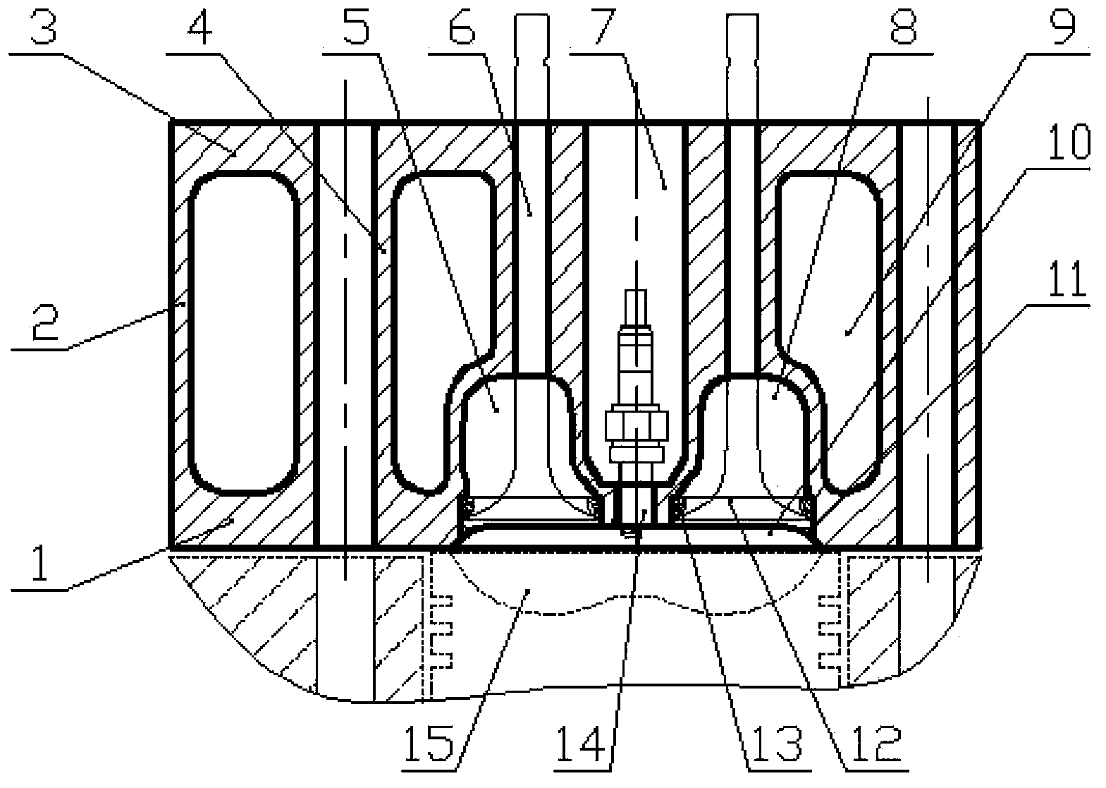
A technology for engine cylinders and natural gas, which is applied to engine components, combustion engines, machines/engines, etc., can solve problems such as lowering the compression ratio, thickness of the cylinder head bottom plate, complex structure of the cylinder head, and the valve chain, so as to improve reliability and reduce Less wear, improved cooling effect

Active Publication Date: 2014-02-12
GUANGXI YUCHAI MASCH CO LTD
View PDF8 Cites 5 Cited by
  • Summary
  • Abstract
  • Description
  • Claims
  • Application Information

AI Technical Summary

Problems solved by technology

[0002] The cylinder head of a traditional natural gas engine usually adopts an open combustion chamber. Due to the small compression ratio of a gas engine, the volume of the combustion chamber is larger than that of a diesel engine. Arranged on the side of the cylinder head, the common practice is to adopt a V-shaped valve arrangement, and set an inverted bowl-shaped combustion chamber at the bottom of the cylinder head. The structure of the cylinder head and valve chain of this structure is complex, and the cylinder head is manufacturable and reliable. sex is relatively poor
However, if a similar diesel engine adopts a vertical valve arrangement, it is necessary to dig deep into the piston and increase the combustion chamber to reduce the compression ratio, which will have a great impact on the reliability of the piston, and the thicker cylinder head bottom plate is not good for heat dissipation

Method used


Image

  • Cylinder cover of natural gas engine
  • Cylinder cover of natural gas engine

Examples


Embodiment Construction

[0016] The specific embodiments of the present invention will be described in detail below in conjunction with the accompanying drawings, but it should be understood that the protection scope of the present invention is not limited by the specific embodiments.

[0017] The cylinder head of the engine is used to close the cylinders and form the combustion chamber. The overhead valve engine cylinder head, in addition to the cooling water jacket, also has valve devices, intake and exhaust passages, etc. The cylinder head belongs to the gas distribution mechanism in the field of internal combustion engines, and is mainly used to close the upper part of the cylinder to form the combustion chamber. And as the support of camshaft and rocker shaft as well as intake and exhaust pipes. The function of the cylinder head is mainly to draw air into the cylinder, and then the spark plug ignites the combustible mixture to drive the piston to do work, and the exhaust gas is discharged from t...


PUM


Abstract

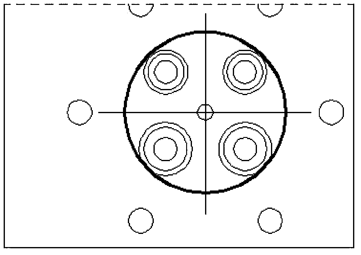
The invention discloses a cylinder cover of a natural gas engine. The cylinder cover is of a frame type cavity structure and comprises an air inlet passage, an air exhaust passage, valve seat ring holes, a saucer-shaped combustion chamber and a spark plug mounting hole. The frame type cavity structure comprises a bottom plate, side plates and a top plate, the air inlet passage and the air exhaust passage are arranged in the middle of a cavity and are respectively communicated with the combustion chamber via valves; the valve seat ring holes are respectively formed in positions among the air inlet passage, the air exhaust passage and the combustion chamber and are used for mounting valve seat rings and forming sealing strips for the heads of the valves; the saucer-shaped combustion chamber is in the shape of an inverted saucer, the size of the outer edge of the saucer-shaped combustion chamber is matched with that of the outer edge of a piston-cup-shaped combustion chamber, and the saucer-shaped combustion chamber and the piston-cup-shaped combustion chamber form an apple-shaped combustion chamber; the spark plug mounting hole is formed in a position between the air inlet passage and the air exhaust passage and is communicated with the saucer-shaped combustion chamber. The cylinder cover has the advantages that owing to the structural design of the saucer-shaped combustion chamber at the bottom of the cylinder cover, the radiating performance of the cylinder cover can be improved, and the reliability of a piston can be effectively enhanced.

Description

technical field [0001] The invention relates to the field of engines, in particular to a cylinder head of a natural gas engine. Background technique [0002] The cylinder head of a traditional natural gas engine usually adopts an open combustion chamber. Due to the small compression ratio of a gas engine, the volume of the combustion chamber is larger than that of a diesel engine. Arranged on the side of the cylinder head, the common practice is to adopt a V-shaped valve arrangement, and set an inverted bowl-shaped combustion chamber at the bottom of the cylinder head. The structure of the cylinder head and valve chain of this structure is complex, and the cylinder head is manufacturable and reliable. sex is relatively poor. However, if a similar diesel engine adopts a vertical valve arrangement, it is necessary to dig deep into the piston and increase the combustion chamber to reduce the compression ratio, which has a great impact on the reliability of the piston, and the ...

Claims


Application Information

Patent Timeline
IPC IPC(8): F02F1/24F02B23/08
CPCY02T10/125Y02T10/12
Inventor 沈捷覃文廖升友覃壮革
Owner GUANGXI YUCHAI MASCH CO LTD
Learn More