
Computer system and method configured for improved cooling

Inactive Publication Date: 2006-01-17
UNISYS CORP
View PDF8 Cites 3 Cited by
  • Summary
  • Abstract
  • Description
  • Claims
  • Application Information

AI Technical Summary

Benefits of technology

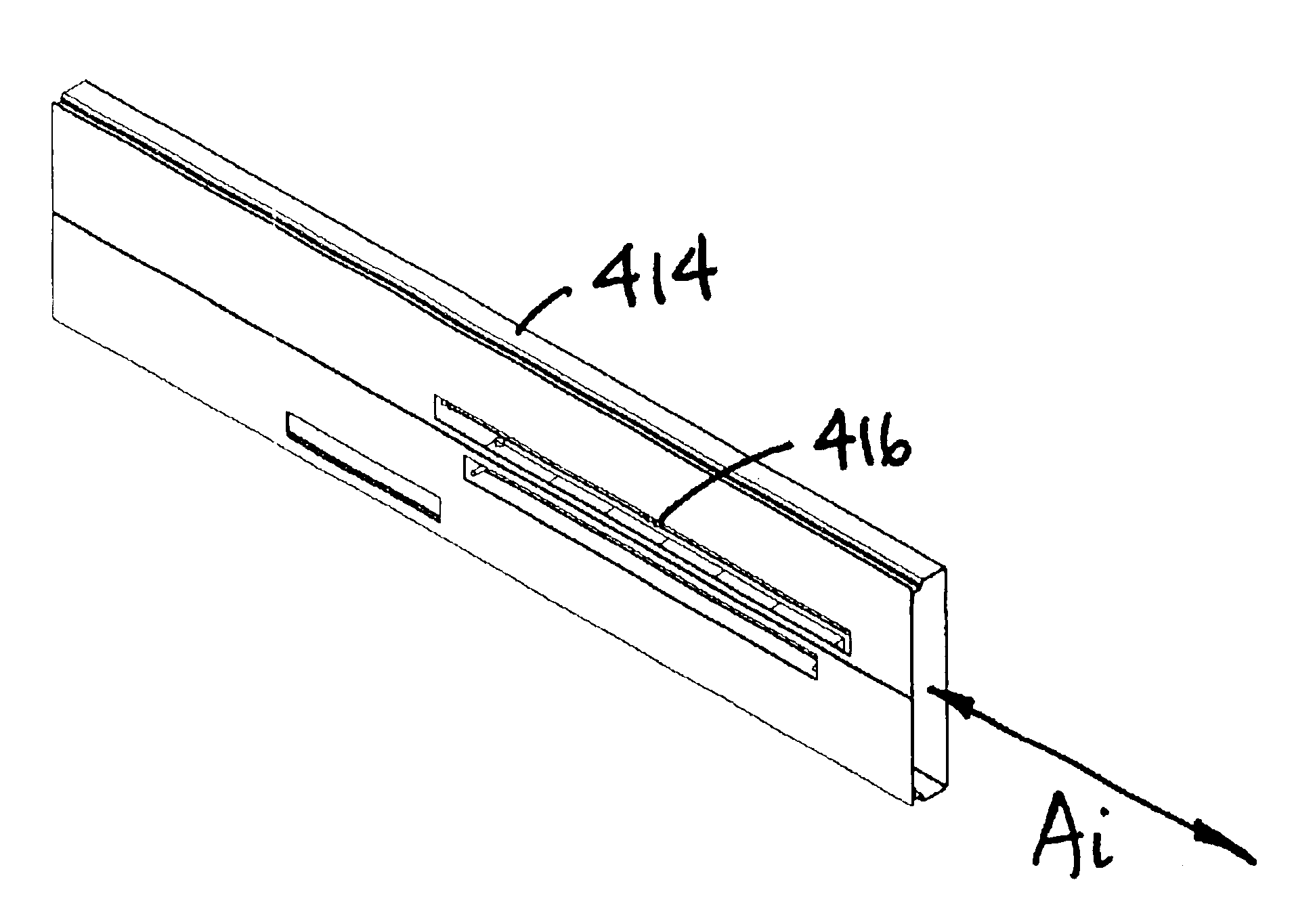
[0008]According to yet another embodiment of this invention, a method is provided for configuring a rack-mounted computer subassembly for improved cooling. The method includes orienting the interconnect assembly in a plane substantially parallel to an insertion axis along which the computer subassembly is inserted into a rack. The

Problems solved by technology

As processor speeds and frequencies increase, the power dissipation of the processors and the supporting circuit assemblies increase dramatically.
Cooling, therefor, is becoming one of the major limitations to the ever-increasing performance of computer systems.
As the temperature of such chips increases, the speed of the chips slows.
Another challenge is raised by the fact that flight times between system elements must decrease in order to increase processor speeds and frequencies.
Accordingly, in such systems, it has become a challenge to keep signal interconnect lengths short enough to meet system timing requirements.
The resulting increase in system density makes it difficult to keep all of the closely-packed elements cool.
The use of such back planes or mid planes can, however, cause a thermal impact in rack-mounted computer designs.
The back plane or mid plane approach can, however, hinder such front-to-back air flow.

Method used


Image

  • Computer system and method configured for improved cooling
  • Computer system and method configured for improved cooling
  • Computer system and method configured for improved cooling

Examples


Embodiment Construction

[0021]Exemplary aspects of the invention will now be described with reference to the figures. It will be appreciated that variations and modifications of the exemplary embodiments illustrated and described herein may be made without departing from the spirit or scope of this invention. For example, the materials, sizes, proportions, and configurations of the illustrated embodiments can be changed, and the illustrated embodiments are not rendered to any specific proportion or scale.

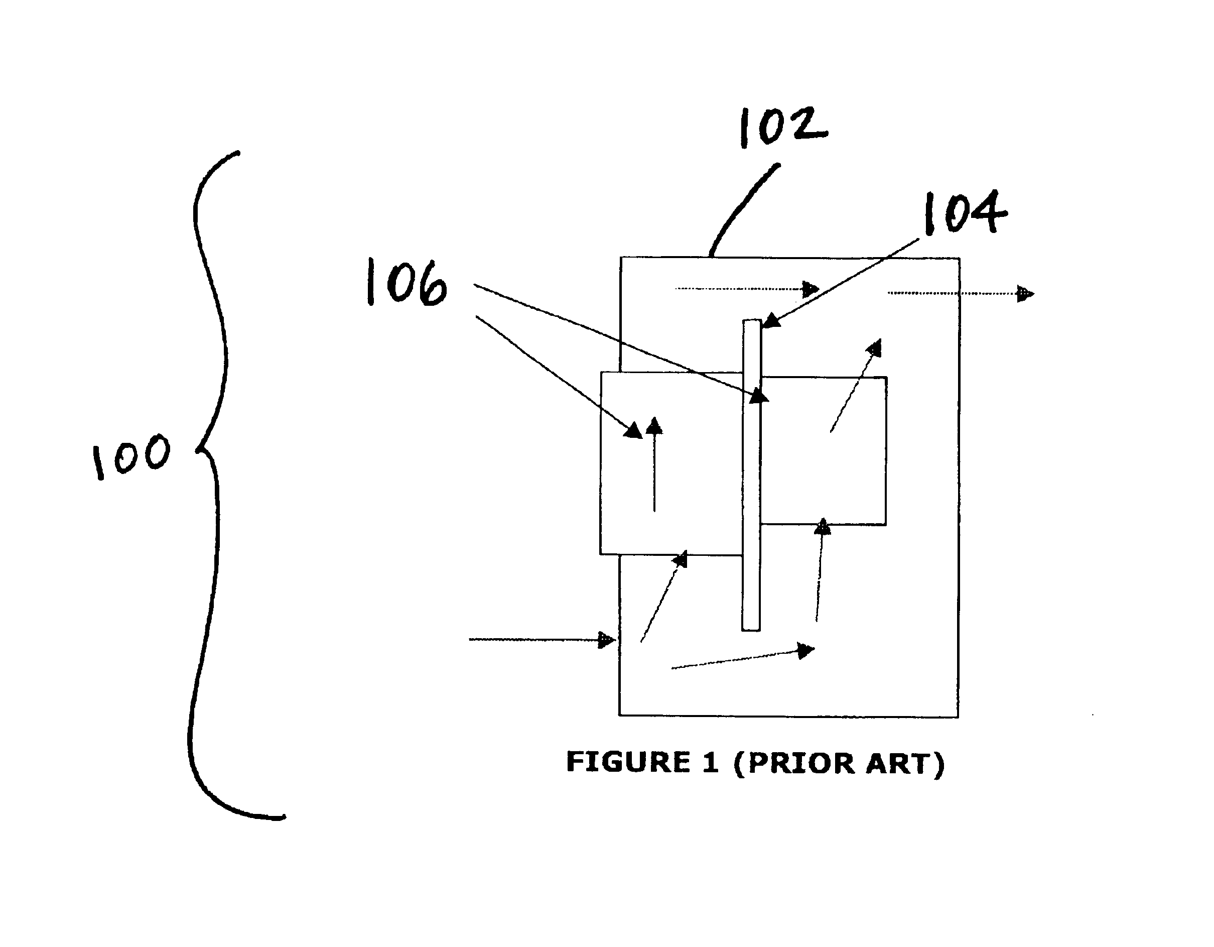
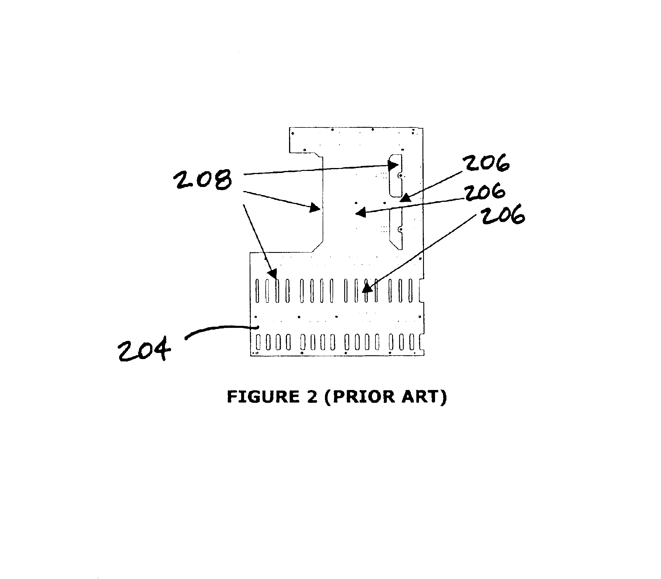
[0022]Referring first to FIGS. 1 and 2, various approaches have been considered to improve the cooling of computer systems. For example, as is illustrated in FIG. 1, a computer subassembly 100 can be provided with a chassis 102 in which a mid plane 104 is mounted. Circuit assemblies 106 (two shown) are mounted to the mid plane 104 for electrical coupling. As is illustrated by the arrows in FIG. 1, air flows from the front (left-hand side of FIG. 1) to the back (right-hand side of FIG. 1) of the computer su...


PUM


Abstract

A computer subassembly is configured to be mounted within a rack along an insertion axis. The computer subassembly includes a chassis configured for insertion into and removal from the rack along the insertion axis, wherein the chassis at least partially defines an interior. An interconnect assembly is mounted within or adjacent the interior of the chassis, and the interconnect assembly is oriented along a plane that is substantially parallel to the insertion axis. At lease one circuit assembly is positioned at least partially within the interior of the chassis and is connected to the interconnect assembly. The circuit assembly is oriented in a plane substantially parallel to the insertion axis. A source of cooling air is positioned to direct cooling air through the interior of the chassis along the insertion axis.

Description

FIELD OF THE INVENTION[0001]This invention relates to a computer system and method configured for improved cooling. In particular, this invention relates to a computer system configured to be mounted within a rack and a method for configuring the computer system for improved cooling of the computer system.BACKGROUND OF THE INVENTION[0002]As processor speeds and frequencies increase, the power dissipation of the processors and the supporting circuit assemblies increase dramatically. Cooling, therefor, is becoming one of the major limitations to the ever-increasing performance of computer systems. Compounding this problem is the fact that the speed of computer chips can be dependent upon their temperature. As the temperature of such chips increases, the speed of the chips slows. Accordingly, there is an increasing need to lower the temperature of such chips.[0003]Another challenge is raised by the fact that flight times between system elements must decrease in order to increase proces...

Claims


Application Information

Patent Timeline
IPC IPC(8): G06F1/20G06F1/18
CPCG06F1/183H05K7/20727G06F1/20
Inventor MEASE, KEITH D.SMITH, GRANT M.
Owner UNISYS CORP
Learn More