Method for using waste heat by separately fetching water from power station condenser
A technology of condenser and power station, applied in the field of machinery, can solve problems such as the inability to start an absorption heat pump device, and achieve the effects of meeting the water temperature requirements of the heating network, the device being simple and easy to operate, and improving the economy.
- Summary
- Abstract
- Description
- Claims
- Application Information
AI Technical Summary
Problems solved by technology
Method used
Image

Examples
Embodiment 1
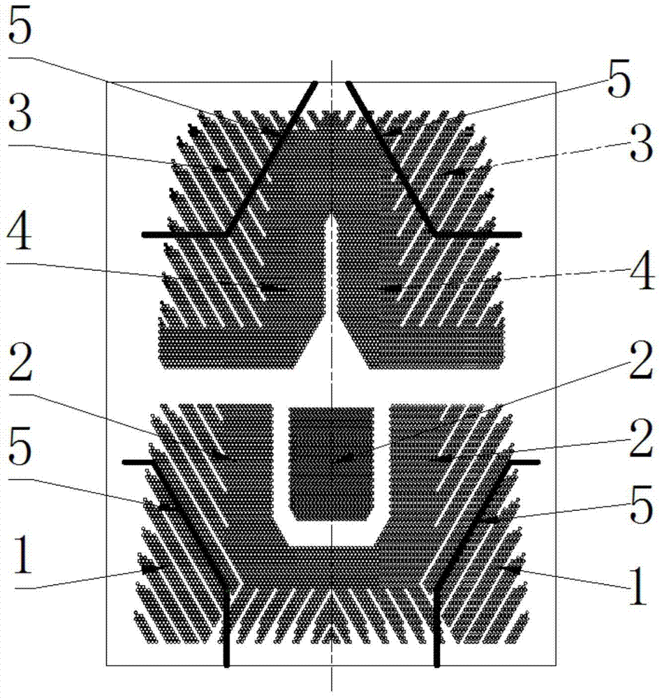
[0017] like figure 1 As shown, for the double-flow condenser, there are front and rear water chambers at the front and rear ends of the condenser shell. The front water chamber is the cooling water inlet and outlet water chamber, which is connected to the front tube plate by bolts , the rear water chamber is the cooling water return water chamber, which is welded with the rear end tube plate, and the front and rear end tube plates are connected with the condenser shell as a whole. Divide the tube bundle in the first process into two high-heat areas 1, and the rest as low-heat areas 2. The high-heat area 1 and the low-heat area 2 are separated by a partition plate 5 in the water chamber; similarly, the second process tube bundle is also divided into Two high heat zones 3 and one low heat zone 4, the high heat zone 3 and the low heat zone 4 are separated by a partition plate 5 in the water chamber, and both tube bundle zones have their own corresponding inlet and outlet water ch...
Embodiment 2
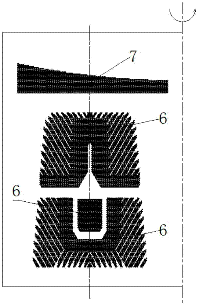
[0019] figure 2 Indicates a tube bundle module on one side of the condenser centerline, and an even number of such tube bundle modules are often symmetrically arranged in the lower shell of the condenser. like figure 2 As shown, for the double-flow condenser, there are front and rear water chambers at the front and rear ends of the condenser shell. The front water chamber is the cooling water inlet and outlet water chamber, which is connected to the front tube plate by bolts , the rear water chamber is the cooling water return water chamber, which is welded with the rear end tube plate, and the front and rear end tube plates are connected with the condenser shell as a whole. Divide the most upstream independent tube bundle of the steam flowing on the shell side of the condenser into a high-heat zone 7, and the rest of the tube bundles as a low-heat zone 6. The water chambers of the high-heat zone 7 and the low-heat zone 6 are independent of each other. Import and export wa...
Embodiment 3
[0021] The specific embodiment can also be a combination of the above scheme 1 and scheme 2. that is figure 2 In addition to the already divided high heat area 7, the original low heat area 6 is divided into similar figure 1 High heat zones 1, 3 and low heat zones 2, 4 are shown in .
[0022] When the condenser of the power station is in operation, the steam entering the condenser from the exhaust port of the steam turbine flows into the tube bundle area along the steam channel around the tube bundle area for condensation and heat exchange, and the remaining uncondensed steam-gas mixture flows into the air cooling area for final condensation and then from The suction port is pumped, thereby establishing and maintaining the vacuum of the steam turbine. When the steam on the shell side of the condenser condenses and releases heat in the high heat area and low heat area, it transfers heat to the heat pump return water and main cooling water on the tube side. The return water ...
PUM
 Abstract
Description
Claims
Application Information
 - R&D
- Intellectual Property
- Life Sciences
- Materials
- Tech Scout
- Unparalleled Data Quality
- Higher Quality Content
- 60% Fewer Hallucinations
Browse by: Latest US Patents, China's latest patents, Technical Efficacy Thesaurus, Application Domain, Technology Topic, Popular Technical Reports.
© 2025 PatSnap. All rights reserved.Legal|Privacy policy|Modern Slavery Act Transparency Statement|Sitemap|About US| Contact US: help@patsnap.com