
Crushing machine for electronic powder material

A technology of bulk materials and shredders, applied in the fields of removing smoke and dust, cleaning methods and utensils, grain processing, etc., can solve the problems of unfavorable working environment, waste of labor resources, harsh environment, etc., to save labor resources and reduce work intensity. , The effect of meeting the requirements of use

Active Publication Date: 2015-03-04
SUZHOU HUIKE EQUIP CO LTD
View PDF7 Cites 19 Cited by
  • Summary
  • Abstract
  • Description
  • Claims
  • Application Information

AI Technical Summary

Problems solved by technology

One of the self-evident shortcomings of manual disintegration is that the labor intensity of the workers is high; the second is that the temperature of the electronic powder materials and saggers coming out of the furnace is as high as 80-120°C, so the environment in which the workers live is harsh. And there is a risk of scalding the workers' limbs; third, due to the low efficiency of manual disintegration, it is difficult to adapt to the firing speed of the electronic kiln, so it is usually dealt with by increasing personnel, resulting in a waste of valuable labor resources; , due to the large amount of dust generated during the crushing process, it is not conducive to the cleanliness of the working environment and affects the health of workers
[0004] Although the technical information of various electronic powder firing kilns can be seen in the published Chinese patent documents, for example, CN102230729B recommends "tunnel kiln structure for sintering electronic products", but there is no enlightenment to eliminate the aforementioned technical problems

Method used


Image

  • Crushing machine for electronic powder material
  • Crushing machine for electronic powder material

Examples


Embodiment Construction

[0019] In order to enable the examiners of the patent office, especially the public, to understand the technical essence and beneficial effects of the present invention more clearly, the applicant will describe in detail the following in the form of examples, but none of the descriptions to the examples is an explanation of the solutions of the present invention. Any equivalent transformation made according to the concept of the present invention which is merely formal but not substantive shall be regarded as the scope of the technical solution of the present invention.

[0020] In the following descriptions, the concepts of up, down, left, right, front and rear directionality or azimuth are all for the position state of the illustration, and the purpose is to facilitate the public to understand the present invention, so it cannot be regarded as For the limitation of the scheme of the present invention.

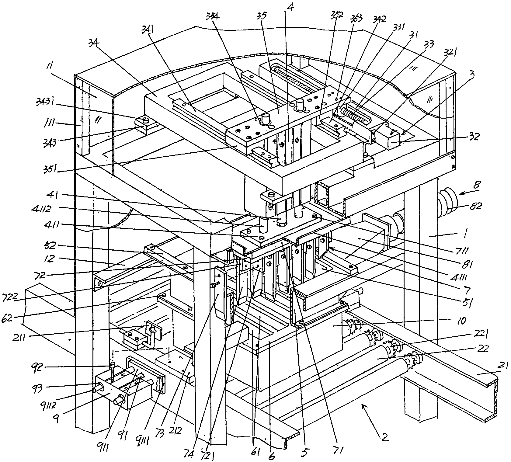
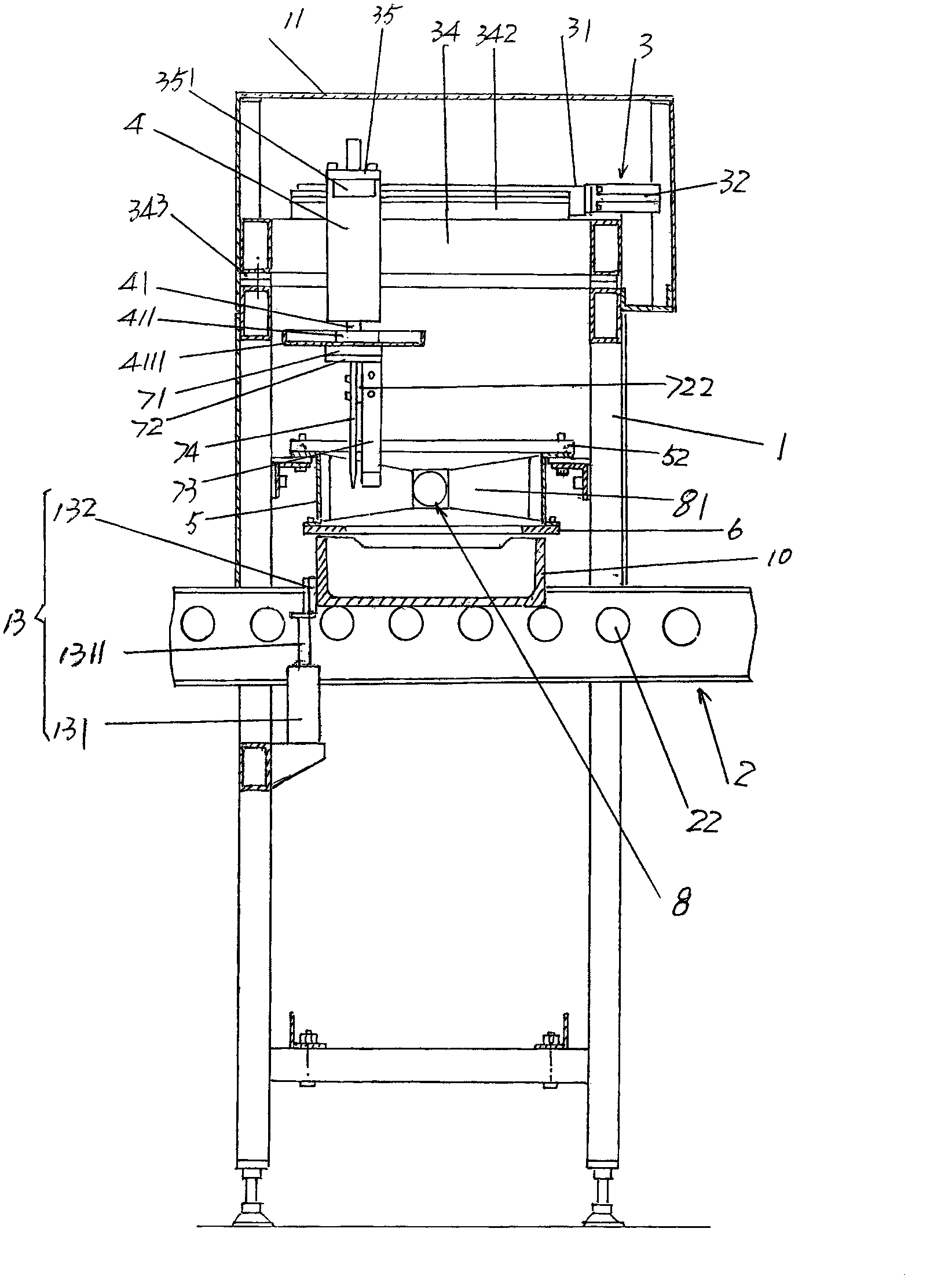
[0021] See figure 1 , provides a frame 1, the frame 1 is a frame-shaped...


PUM


Abstract

The invention relates to a crushing machine for an electronic powder material, belonging to the technical field of supporting facilities of an electronic kiln. The crushing machine for the electronic powder material comprises a machine frame, wherein the machine frame follows a saggar conveying mechanism of an automatic production flow line of an electronic kiln; a crushing action cylinder horizontal displacement mechanism is arranged on the top of the machine frame; a crushing action cylinder is connected with the crushing action cylinder horizontal displacement mechanism; a saggar mouth edge part enclosing pallet is fixed on the machine frame; a crushing blade scraping plate is fixed at the bottom of the saggar mouth edge part enclosing pallet; a crushing mechanism is connected with a crushing action cylinder column and corresponds to the crushing blade scraping plate; a dust leading-out mechanism is connected with the saggar mouth edge part enclosing pallet; a pair of saggar clamping action cylinders are arranged on the saggar conveying mechanism in a face-to-face state and correspond to the positions below the two corresponding sides of the crushing blade scraping plate. According to the crushing machine for the electronic powder material, the operation intensity is alleviated, scalding phenomenon is avoided, the efficiency is high, labor resources are saved, a clean environment is guaranteed, and the using requirement of the automatic production flow line of the electronic kiln can be met.

Description

technical field [0001] The invention belongs to the technical field of electronic kiln supporting facilities, and in particular relates to an electronic powder material disintegrator, which is installed on the automatic production line of the electronic kiln, and is used for electronic powder that has been fired and discharged from the sagger of the electronic kiln. Body material disintegrated. Background technique [0002] Electronic powder materials mentioned above such as color phosphor, lamp powder, barium titanate, strontium titanate, yttrium trioxide, titanium dioxide, zirconia, alumina, bismuth oxide, lead zirconate titanate, lithium iron phosphate or iron Oxygen magnetic powder, etc. These materials (that is, electronic powder materials) that are not limited to the examples usually need to be loaded into the sagger after weighing and metering and transported into the furnace by the automatic feeding device of the electronic kiln, that is, introduced into the furnac...

Claims


Application Information

Patent Timeline
Patent Type & Authority Patents(China)
IPC IPC(8): B02C18/02B02C18/16B02C18/22B08B15/04
Inventor 陈龙豪惠文斌赵泉陈斌
Owner SUZHOU HUIKE EQUIP CO LTD
Learn More