
Testing device for mechanical property of material

A testing device and a technology of material mechanics, applied in the direction of measuring devices, analytical materials, scientific instruments, etc., can solve problems such as clamping difficulties, single test methods, and inability to conduct in-depth research on the combination of composite loads and material denaturation damage processes. To achieve the effect of compact structure and high degree of compounding

Inactive Publication Date: 2014-01-01
JILIN UNIV
View PDF4 Cites 40 Cited by
  • Summary
  • Abstract
  • Description
  • Claims
  • Application Information

AI Technical Summary

Problems solved by technology

[0005] At the same time, in the existing composite load testing device and research that can be used for in-situ observation, it is mainly for the testing of micro-scale components such as low-dimensional materials, which needs to be completed by complex methods such as imaging systems such as scanning electron microscopes and focused ion beams. The clamping of micro-devices is mainly realized based on complex processes such as MEMS micro-electromechanical systems; if it is to test micro-scale components of thin-film materials such as carbon nanotubes, wires or strips with prefabricated gaps, it needs to be realized with the help of substrate materials The synthesis and growth of samples often require complex processes such as corrosion and deposition, and because the substrates used to attach thin film materials are often hard and brittle materials, it is difficult to clamp, so the mechanical tests on such materials are mostly uniaxial compression test, the test method is relatively simple
[0006] For the composite load test of three-dimensional specimens with characteristic dimensions above centimeters, without in-situ observation with imaging equipment, it is impossible to carry out in-depth research on the combination of composite loads, micromechanical behavior of materials and degenerative damage process

Method used


Image

  • Testing device for mechanical property of material
  • Testing device for mechanical property of material
  • Testing device for mechanical property of material

Examples


Embodiment Construction

[0029] Embodiments of the present invention will be described in detail below in conjunction with the accompanying drawings.

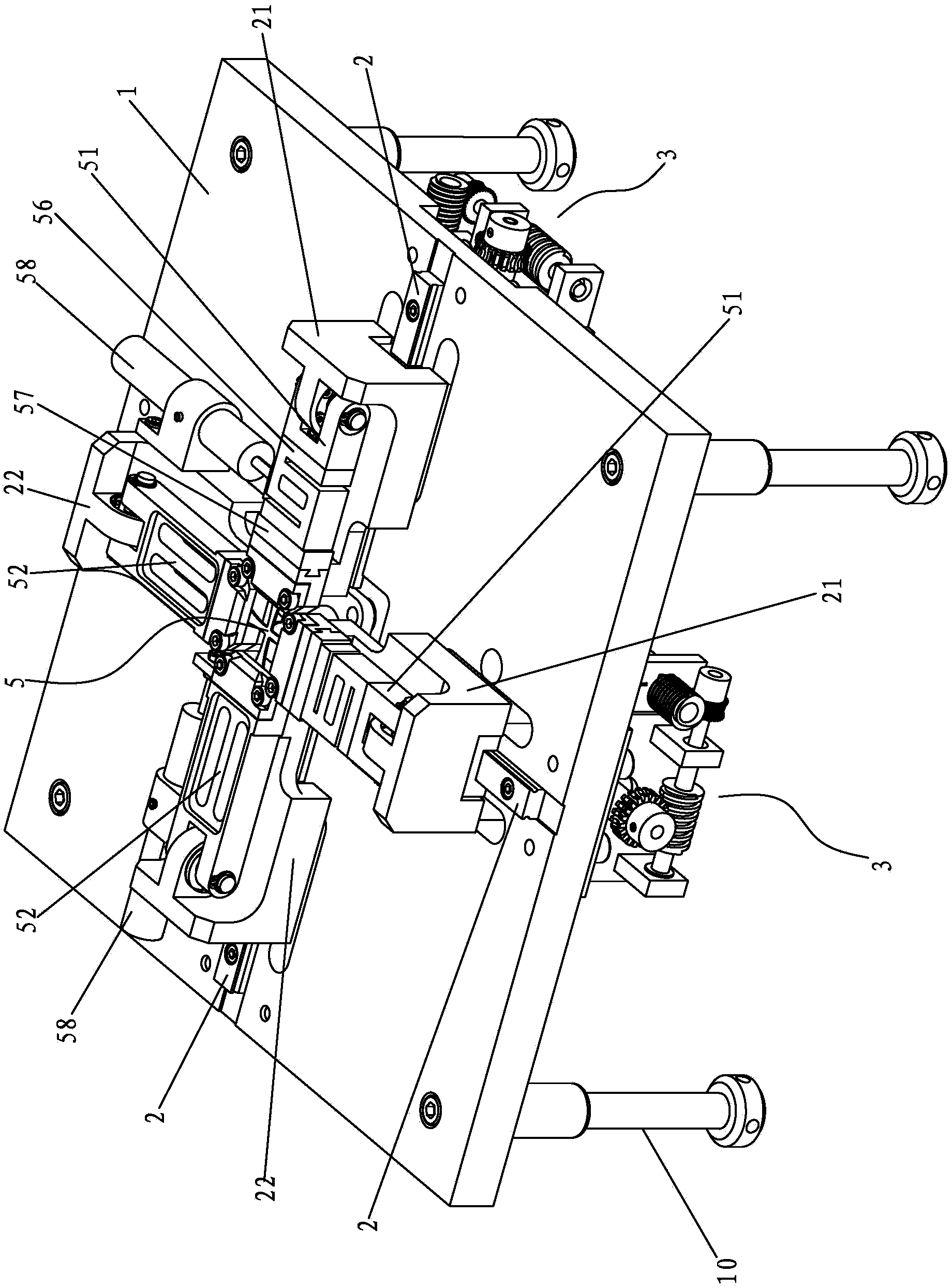
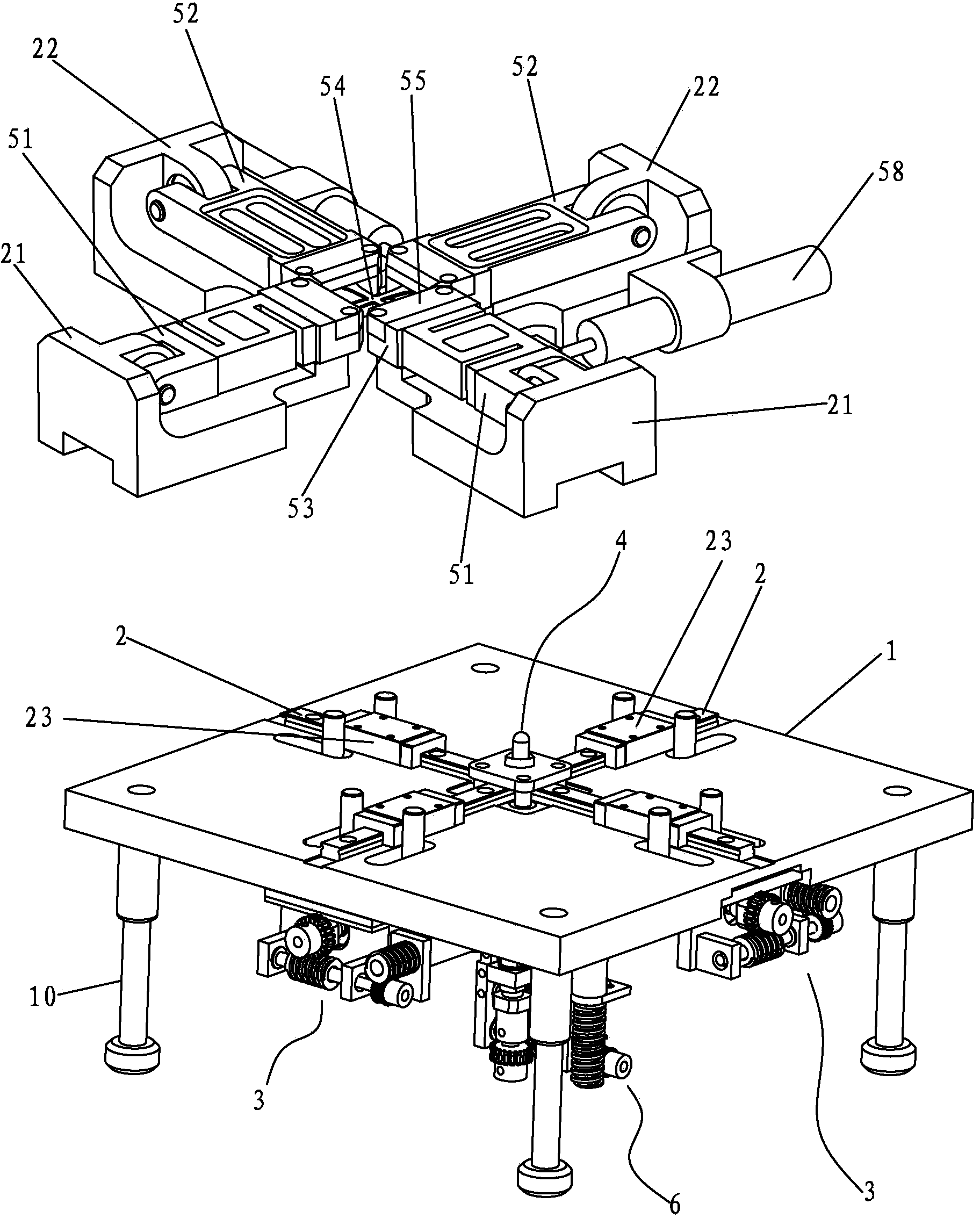
[0030] A device for testing mechanical properties of materials in the present invention includes a working platform 1 provided with supporting feet 10 for supporting, on the working platform 1 there are slide rails 2 perpendicular to each other along the X-axis and Y-axis directions, and along the X-axis The slide rail 2 arranged in the direction and the slide rail 2 arranged along the Y-axis direction are provided with a first stretching seat 21 and a second stretching seat 22 for stretching the specimen, and on the back of the working platform 1 there is a A stretching seat 21 and a second stretching seat 22 move toward or back to the tensile load driving device 3, and the first stretching seat 21 and the second stretching seat 22 arranged along the X-axis and Y-axis directions are connected There is a clamping device 5 for clamping the test piece. B...


PUM


Abstract

The invention discloses a testing device for a mechanical property of a material. Slide rails vertical to each other are arranged on a working platform along the X axis and the Y axis; a first drawing seat and a second drawing seat for drawing a test piece are arranged on the slide rails along the X-axis direction and / or the Y-axis direction; a clamping device is arranged between the first drawing seat and the second drawing seat; a bending mechanism for applying bending load to the test piece along a Z direction is arranged below the clamping device; a tensile load is applied to the test piece through a control tensile load driving device; a bending load is applied to the test piece through a control bending load driving device; the testing on the mechanical property of the material in a biaxial drawing and bending composite load mode can be realized on the test piece; the provided composite load mode conforms to the stress level of the test piece under the actual working condition. Meanwhile, pure tensile test and pure three-point bending test can also be performed; biaxial drawing load and three-point bending load can be loaded independently or loaded in sequence; the testing device has the characteristics of compact structure and high compound degree.

Description

【Technical field】 [0001] The invention relates to material mechanics experiment equipment, in particular to a material mechanics performance testing device capable of realizing biaxial stretching and bending composite load modes under a microscope. 【Background technique】 [0002] In actual working conditions, materials and their products are often subjected to multiple loads, and it is difficult for a single-load mechanical testing device to accurately test the loading form of materials and their products under actual working conditions, that is, it is impossible to test the material under the combined load. accurate evaluation of its mechanical properties. [0003] In the existing research, the loading of the composite load mode is mainly realized by irregular clamping of the specimen and the tensile axis at an angle to each other. The loading force output by the driving source is mainly the axial tensile force. The unequal-height tension mode makes composite load tests su...

Claims


Application Information

Patent Timeline
IPC IPC(8): G01N3/00
Inventor 李海连赵宏伟马志超张攀峰吴庆玲崔利娜李士兵张培馨
Owner JILIN UNIV
Learn More