
Movable coal synthesis gas metnanation catalyst testing platform and testing method

A test platform and catalyst technology, applied in chemical instruments and methods, inorganic chemistry, gas fuel, etc., to achieve the effects of convenient transportation, strong applicability, and easy miniaturization

Active Publication Date: 2013-12-25
HUANENG CLEAN ENERGY RES INST +1
View PDF6 Cites 4 Cited by
  • Summary
  • Abstract
  • Description
  • Claims
  • Application Information

AI Technical Summary

Problems solved by technology

Furthermore, most of the currently developed complete methanation catalysts are in the laboratory research stage. In the future, a large number of industrial pilot tests will be needed to compare and optimize catalysts and determine the best process parameters. Generally speaking, only catalysts that have been stably operated for thousands of hours can Entering the stage of large-scale industrialization

Method used


Image

  • Movable coal synthesis gas metnanation catalyst testing platform and testing method
  • Movable coal synthesis gas metnanation catalyst testing platform and testing method
  • Movable coal synthesis gas metnanation catalyst testing platform and testing method

Examples


specific example

[0053] The following gas components are all volume percentages.

example 1

[0055] In this example, the coal gas produced by the Shell gasifier is used as the gas source, and its gas components are shown in Table 1 below:

[0056] Table 1

[0057] CO 2 2.98% CO 51.19% H 2 23.15% N 2 8.34% Ar 0.10% h 2 S 0.13% COS 0.01% HCN 0.002 CH 4 0.77% NH 3 0.01% h 2 o 13.33%

[0058] 1) The sulfur-resistant water gas conversion device changes the ratio of hydrogen to carbon monoxide in the gas to an appropriate value

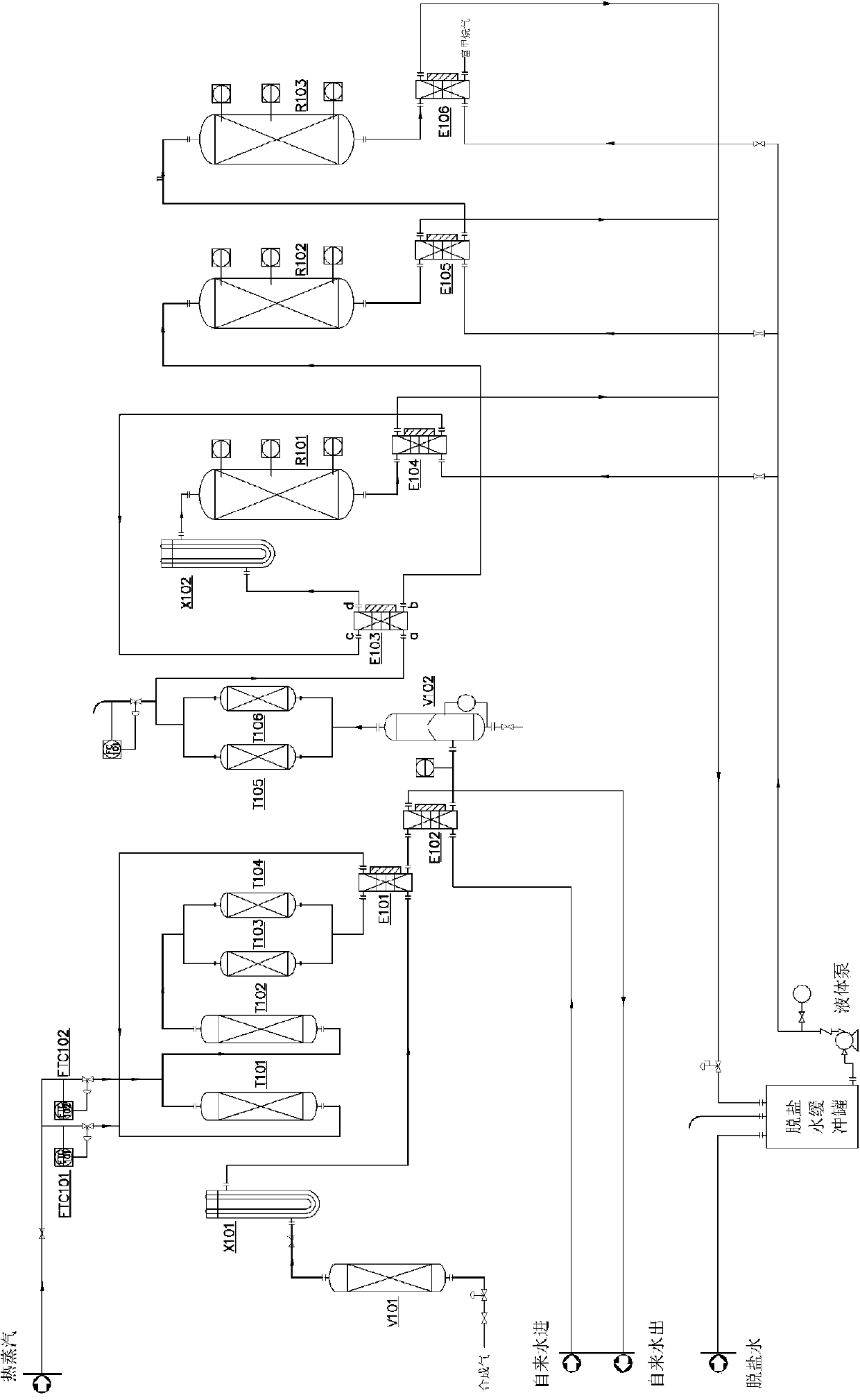
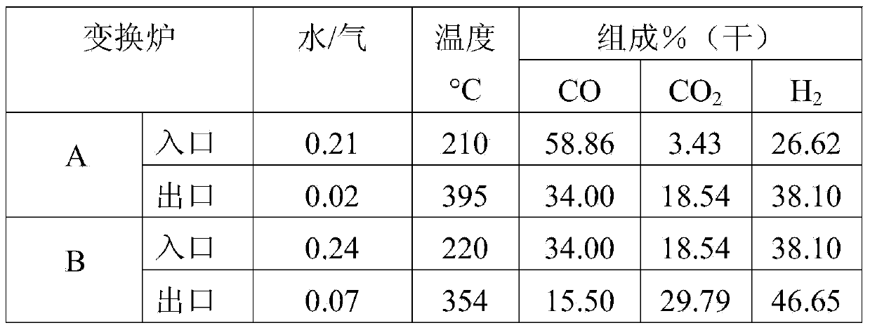
[0059] The gas temperature is 160°C and the pressure is 2.8Mpa. gas at 3Nm 3 The flow rate of / h first passes through the gas buffer tank V101 to remove most of the moisture. Then it is heated to 200°C by the electric heating preheater AX101, and the flowmeter FTC101 is instructed to add water vapor. The volume ratio of water vapor and gas is 0.21. After mixing, it enters the converter furnace A T101. Indicate and control the flowmeter FTC102 to add water vapor, the...

example 2

[0073] This example uses the coal gas produced by the Lurgi gasifier as the gas source. Its gas composition is shown in Table 4 below:

[0074] Table 4

[0075] CO 2 2.98% CO 43.19% H 2 22.15% N 2 8.34% Ar 0.10%

[0076] h 2 S 0.13% COS 0.01% HCN 0.002 CH 4 9.87% NH3 0.01% h 2 o 13.33%

[0077] 1) The sulfur-resistant water gas conversion device changes the ratio of gas hydrogen to carbon monoxide to an appropriate value

[0078] The gas temperature is 160°C and the pressure is 2.8Mpa. Gas at 2.5Nm 3 The flow rate of / h first passes through the gas buffer tank V101 to remove most of the moisture. Then it is heated to 200°C by the electric heating preheater A X101, the flowmeter FTC101 is instructed to add water vapor, the volume ratio of water vapor and gas is 0.21, and after mixing, it enters the converter A T101, and the gas transformed by the converter A is instructed Control the f...


PUM


Abstract

The invention discloses a movable coal synthesis gas metnanation catalyst testing platform and a testing method. The testing platform comprises a gas component conversion and purification part and a gas methanation part which can be transported in a container, wherein the gas component conversion and purification part comprises a sulfur water resistant coal gas conversion device, a moderate temperature zinc oxide desulfurization device, a gas-water separation device, and an NaOH and 5A molecular sieve column decarbonization device; and the gas methanation part is a three-section methanation reactor device. The testing method comprises the steps that 1, the sulfur water resistant coal gas conversion device converts a ratio of hydrogen to carbon monoxide in coal gas into an appropriate value; 2, the moderate temperature zinc oxide desulfurization device reduces sulfur content to below 0.2ppm; 3, the gas-water separation device separates water in the coal gas; 4, the NaOH and 5A molecular sieve column decarbonization device performs decarbonization to enable the content of carbon to be below 20 ppm; and 5, the three-section methanation reactor device performs coal gas methanation reaction. The platform is used for testing an optimal methanation reaction condition of various gas source conditions, adapts to testing of different virgin gas components, different operation conditions and different catalysts, and can test and evaluate a methanation technology, an operation parameter and catalyst performance.

Description

technical field [0001] The invention relates to the technical field of coal-to-natural gas, in particular to a movable coal-to-synthesis gas methanation catalyst test platform and a test method. Background technique [0002] my country's energy structure is "more coal, less oil, and gas", with insufficient oil and gas resources and relatively rich coal resources. During the combustion of coal, a large amount of sulfur oxides, nitrogen oxides, and dust pollution are emitted, which can cause acid rain, photochemical smog and other weather pollution. Dust, especially PM2.5, can cause human respiratory diseases. my country is in the mid-to-late stage of industrialization, and the energy demand is huge, and the discharge of pollutants is also intensified, resulting in frequent environmental incidents. Therefore, we must pay attention to environmental protection, promote energy conservation and emission reduction, and convert coal efficiently and cleanly to meet the requirements ...

Claims


Application Information

Patent Timeline
Patent Type & Authority Applications(China)
IPC IPC(8): C10L3/08C01B3/16C01B3/50C01B3/56
Inventor 王晓龙肖天存徐越赵志国许世森
Owner HUANENG CLEAN ENERGY RES INST
Learn More