
A gas absorption system and its application

A gas absorption and absorption tower technology, which is used in the separation of dispersed particles, chemical instruments and methods, separation methods, etc., can solve the problems of low absorption efficiency, explosion risk, and inability to automate gas control, and achieves reduction of emissions and work intensity. , the effect of easy automation

Active Publication Date: 2015-09-30
TSINGHUA UNIV
View PDF2 Cites 0 Cited by
  • Summary
  • Abstract
  • Description
  • Claims
  • Application Information

AI Technical Summary

Problems solved by technology

[0003] Facing the development trend of high-temperature gas-cooled reactors, the production of fuel elements is moving toward large-scale. The original laboratory system has a gas-into-liquid cavity structure, which has low absorption efficiency, cannot be automatically controlled, and the gas is easily mixed with air to cause explosion hazards, which cannot meet the requirements. There is an urgent need for a set of efficient, continuous operation, easy automatic control, safe and reliable gas absorption equipment that meets production requirements

Method used


Image

  • A gas absorption system and its application

Examples


Embodiment 1

[0031] Example 1: Gas Absorption System

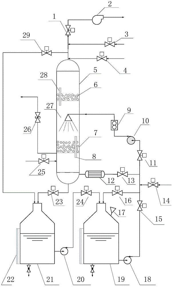
[0032] Including absorption tower 5, lye tank 19, secondary liquid tank 21, gas pipeline 25 to be absorbed; the top of the absorption tower is provided with a pipeline, which is connected with an emptying pipeline (fan 2 is arranged on the emptying pipeline), argon gas The pipeline 3, the clear water pipeline 4 and the overflow pipe 29; the overflow pipe 29 is connected to the secondary liquid tank 21; the positions of the emptying pipeline, the non-oxidizing gas pipeline, the water pipe and the overflow pipe are sequentially from top to bottom.

[0033] The absorption tower 5 is equipped with dispersed packing 7 (randomly stacked Pall rings) and defoaming packing 6 (random corrugated plate packing), and the defoaming packing 6 is located above the dispersed packing 7, and a spray nozzle 27 is arranged between the two packings , the nozzle is connected to the lye tank 19. The secondary liquid tank 21 is connected to the lye tank 19 th...

Embodiment 3

[0057] System and steps are the same as in Example 2.

[0058] Use it for nuclear fuel UO 2 The specific coating process of particles, that is, H 2 Alkali absorption process of mixed gas with HCl. It is measured that the gas to be absorbed is H containing 35% (volume fraction) of hydrogen chloride (HCl) gas 2 Mixed gas with HCl, the gas velocity is 110L / min. Saturated NaOH solution is prepared in the lye tank, PH=14. During normal absorption operation, the lye circulation rate is 25L / min, the absorption efficiency is more than 95%, and the HCl content in the exhaust gas is less than 1% (volume fraction).


PUM


Abstract

The invention belongs to the field of gas separation and provides a gas absorption system. The gas absorption system comprises an absorption tower, an alkaline liquid tank, a secondary liquid tank and a to-be-absorbed gas pipeline, wherein a pipeline is arranged on the top of the absorption tower; an evacuation pipeline, a non-oxidizing gas pipeline, a water pipe and an overflow pipe are connected to the pipeline; the overflow pipe is connected with the secondary liquid tank; distributed filling and de-foaming filling are arranged in the absorption tower; the secondary liquid tank is connected with the alkaline liquid tank through the pipeline and a pump and is connected with the tower bottom of the absorption tower through the pipeline; the to-be-absorbed gas pipeline enters the absorption tower from a position below the distributed filling in the absorption tower. The absorption tower of the gas absorption system provided by the invention is divided into three main spaces by the distributed filling and the de-foaming filling, the gas-liquid reverse flow operation is realized, the relatively good absorption efficiency is obtained, the emission of harmful gas is reduced, and the gas absorption system is easy to automatically operate and can continuously run.

Description

technical field [0001] The invention belongs to the field of gas separation, and in particular relates to a system for separating harmful gas from gas and the application of the system. Background technique [0002] The ceramic fuel element used in my country's pebble bed high temperature gas-cooled reactor has a structure of spherical coated particles (TRISO) dispersed in the graphite matrix of the fuel zone. The first guarantee of the inherent safety of the high-temperature gas-cooled reactor nuclear power plant is that the nuclear fuel used is TRISO-type coated particles, which consists of a nuclear fuel core, a loose pyrolytic carbon layer, an inner dense pyrolytic carbon layer, a silicon carbide layer and an outer layer. Dense pyrolytic carbon layer composition. The above cladding layer can well prevent the fission products from escaping the fuel particles at the design temperature. The most critical layer is the SiC layer, which is responsible for preventing the relea...

Claims


Application Information

Patent Timeline
Patent Type & Authority Patents(China)
IPC IPC(8): B01D53/78B01D53/68
Inventor 刘马林刘兵邵友林朱钧国张秉忠杨冰
Owner TSINGHUA UNIV
Learn More