A method for purifying flue gas from a gas-fired internal combustion engine

A gas-fired internal combustion engine and flue gas purification technology, applied in the direction of internal combustion piston engine, combustion engine, exhaust gas treatment, etc., can solve the problems of unfavorable reduction reaction denitration process, high nitrogen oxide concentration, high nitrogen oxide emission concentration, etc. Denitration efficiency and effective use of ammonia, reduction of denitration costs, and effects of low ammonia leakage

Inactive Publication Date: 2015-10-21
NANJING UNIV
View PDF3 Cites 0 Cited by
  • Summary
  • Abstract
  • Description
  • Claims
  • Application Information

AI Technical Summary

Problems solved by technology

[0005] The first is the high concentration of nitrogen oxide emissions, which is due to the fact that gaseous fuels are easy to achieve full combustion, which makes the combustion temperature high, resulting in a high concentration of nitrogen oxides in the flue gas
Secondly, because the working process of the gas internal combustion engine is intermittent, the exhaust gas flow rate, concentration, etc. present periodic pulsation characteristics, which has a negative impact on the application of denitrification technology, which is usually in a continuous flow state.
[0006] In addition, gas-fired internal combustion engines generally adopt lean combustion technology, resulting in high oxygen content in the flue gas, usually greater than 8%, making the flue gas present a strong oxidizing atmosphere, which is also not conducive to the denitrification process as a reduction reaction.

Method used


Image

  • A method for purifying flue gas from a gas-fired internal combustion engine

Examples


Embodiment Construction

[0019] The present invention will be further described below in conjunction with accompanying drawing:

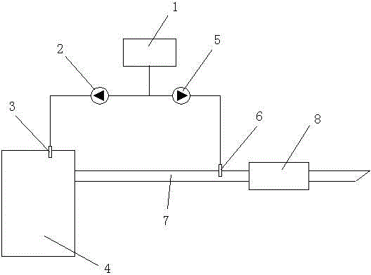
[0020] The present invention includes cylinder head denitrification and flue denitrification, and the system structure schematic diagram that it adopts is as attached figure 1 As shown, the cylinder head denitrification is to pressurize the ammonia gas in the ammonia tank 1 to a pressure of more than 10 kg through the cylinder head injection pump 2 to enter the cylinder head injector 3, and the cylinder head injector 3 controls its opening and closing by a signal, and the Ammonia is injected into the exhaust branch pipe near the combustion chamber of the engine 4 or the exhaust valve. The flue denitrification is to pressurize the ammonia gas in the ammonia tank 1 to a pressure of more than 10 kg through the flue injection pump 5 and enter the flue injector 6, and the flue injector 6 then injects the ammonia gas into the exhaust pipe 7 of the engine middle. The cylinder he...


PUM


Abstract

The invention discloses a method for purifying smoke of a gas internal combustion engine. The method is characterized by comprising the following steps of: cylinder head denitration and flue denitration, wherein cylinder head denitration is as follows: the ammonia gas is pressurized to pressure of over 10 kilograms by virtue of a cylinder head ejector pump and enters into a cylinder head ejector, the opening and closing of the cylinder head ejector are controlled by signals, and the cylinder head ejector ejects the ammonia gas into an engine combustion chamber or an exhaust branch nearby an exhaust valve; and flue denitration is as follows: the ammonia gas is pressurized to the pressure of over 10 kilograms by virtue of a flue ejector pump and enters into a flue ejector, and then the flue ejector ejects the ammonia gas to a smoke discharging pipe of an the engine. The method disclosed by the invention is applicable to a gap type working mode of the internal combustion engine, can be used for effectively carrying out purifying treatment on the smoke of the gas internal combustion engine, so that the smoke meets the environmental protectionly-friendly requirements better.

Description

technical field [0001] The invention relates to a method for purifying flue gas of a gas internal combustion engine. Background technique [0002] Gas generator set refers to the power generation equipment that uses natural gas, coal bed methane, biogas, landfill gas, straw gasification gas, blast furnace gas, coke oven gas and other gas as fuel, uses internal combustion engine as combustion device and drives generator to output electric energy. Gas-fired generator sets are widely used in the fields of energy saving, emission reduction and new energy utilization. They belong to the development direction encouraged by the state and have developed rapidly in recent years. With the comprehensive advancement and continuous deepening of flue gas denitrification work in thermal power plants in my country, it has become a new field of flue gas denitrification for the gas-fired internal combustion engine power generation industry with small power generation but a large number. [0...

Claims


Application Information

Patent Timeline
Patent Type & Authority Patents(China)
IPC IPC(8): F01N3/28F01N9/00
CPCY02T10/40
Inventor 陈泽智龚惠娟王梦秋吴未立王卫星徐明刚
Owner NANJING UNIV
Why Eureka
Try Eureka