
Image method measuring device and method for gas-liquid two-phase flow in pipelines

A gas-liquid two-phase flow and measurement device technology, which is applied in the direction of measurement devices, material analysis through optical means, instruments, etc., can solve problems such as inability to obtain, flow interference, and inability to obtain multiple parameters at the same time, so as to improve reliability Effect

Active Publication Date: 2013-12-04
UNIV OF SHANGHAI FOR SCI & TECH
View PDF7 Cites 27 Cited by
  • Summary
  • Abstract
  • Description
  • Claims
  • Application Information

AI Technical Summary

Problems solved by technology

Existing measurement methods include separation measurement method, impedance method, extinction method, etc., or cause certain interference to the flow, or are greatly affected by flow state, temperature, and impurities, and cannot obtain multiple parameters at the same time
In recent years, with the development of digital cameras and computer technology, two-phase flow image measuring instruments that use digital cameras to photograph two-phase flow processes to obtain relevant information have been gradually developed. However, high-speed photography is usually only used for flow pattern determination. Detailed information including droplet particle size and distribution, droplet velocity and distribution, droplet concentration and flow rate, and liquid film thickness cannot be obtained yet

Method used


Image

  • Image method measuring device and method for gas-liquid two-phase flow in pipelines
  • Image method measuring device and method for gas-liquid two-phase flow in pipelines
  • Image method measuring device and method for gas-liquid two-phase flow in pipelines

Examples


Embodiment 2

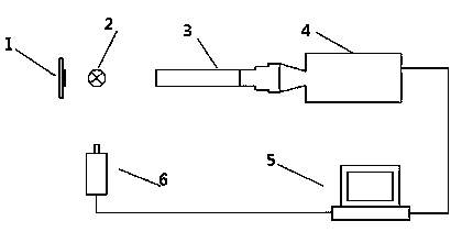
[0035] Such as figure 2 As shown, for the opaque pipe section, the corresponding transparent window 7 is processed and connected to the pipe section, so that the shape and size of the channel in the window are the same as the shape and size of the inner wall of the pipe, that is, the window 7 is used to replace the transparent pipe 2. The measurement steps are the same as in Example 1. The process is the same.

[0036] In the above two embodiments, the illumination light source adopts halogen light source, xenon light source or semiconductor light source; laser light source adopts visible light laser; telecentric lens adopts zoom or non-zoom telecentric lens; image sensor adopts CCD or CMOS devices.


PUM


Abstract

The invention discloses an image method measuring device and method for gas-liquid two-phase flow in pipelines. The image method measuring method is characterized by comprising the steps of using a light source to light liquid drop to be tested through a transparent pipeline or a window, using a laser light source to light the liquid film level, using a telecentric lens and a CCD or CMOS image sensor to image liquid drop or liquid film in an area to be tested, comparing the out-of-focus blur radius of one single liquid drop image with the allowed confusion circle size of a measuring system to remove liquid drop images out of a camera lens focus depth range, processing an image of movable liquid drop in the focus depth range to extract the particle size, the speed and the direction, carrying out statistics on a lot of liquid drop to obtain the particle size distribution in the area to be tested, the speed distribution in the area to be tested, the average volume concentration in a statistic period in the area to be tested and the average volume flow rate in the statistic period in the area to be tested, and determining the thickness of the liquid film according to the distance between the liquid level of the liquid film image and the pipe wall. The image method measuring method has the advantages of only using one set of system to achieve the purpose of simultaneously measuring multiple parameters of the gas-liquid two-phase flow in the pipelines, simplifying the measuring system and reducing measuring cost.

Description

Technical field [0001] The invention relates to a gas-liquid two-phase flow measurement device and method in a pipeline, in particular to a method for obtaining the particle size and distribution of liquid droplets in a gas-liquid two-phase flow in a pipeline based on a single-frame single-exposure image method, and the droplet velocity and Apparatus and methods for distribution, droplet concentration and flow rate, and liquid film thickness. Background technique [0002] Gas-liquid two-phase flow in pipes is a very important flow form in two-phase flow, which is widely used in energy, power, oil and gas, chemical industry and other fields. The detection of its cross-sectional phase holdup and other parameters is useful for understanding the law of two-phase flow and rational development of resources. Utilization, safe production and industrial process control are all of great significance. The existing measurement methods include separation measurement method, impedance method,...

Claims


Application Information

Patent Timeline
IPC IPC(8): G01N21/84G01N21/01
Inventor 周骛蔡小舒
Owner UNIV OF SHANGHAI FOR SCI & TECH
Learn More