Device for the treatment of a liquid or gaseous medium by means of uv radiation
a technology of ultraviolet radiation and gaseous medium, which is applied in the direction of ohmic-resistance heating devices, water/sludge/sewage treatment, lavatory sanitory, etc., can solve the problems of limiting the operating pressure of the device significantly, requiring a very high energy of the uv radiation source, and the known device has a small space. , the effect of low design
- Summary
- Abstract
- Description
- Claims
- Application Information
AI Technical Summary
Benefits of technology
Problems solved by technology
Method used
Image
Examples
first embodiment
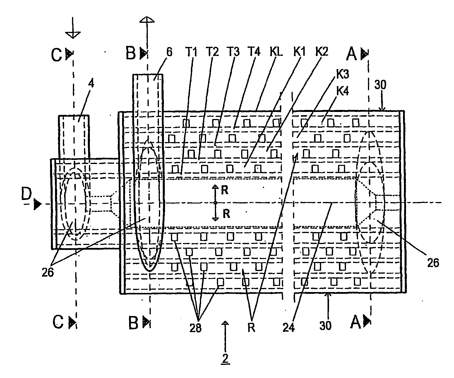
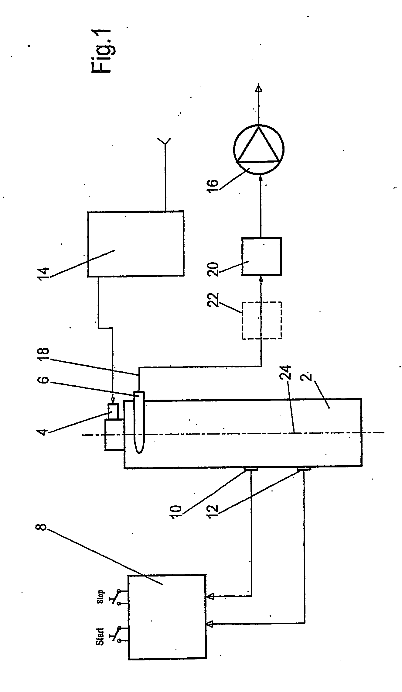
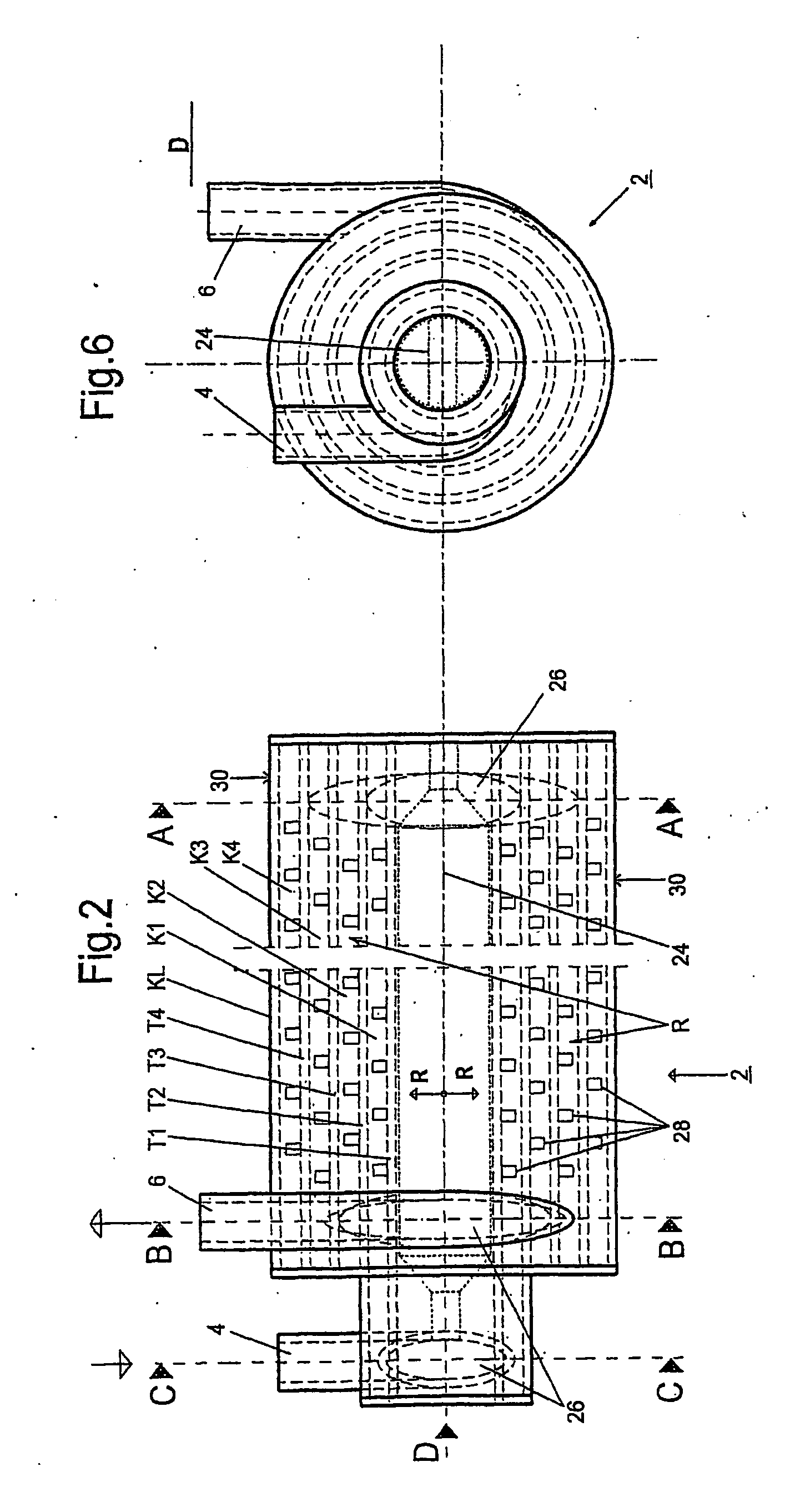
[0034]FIG. 1 shows a schematic block diagram of a device according to the invention for treating a liquid or gaseous medium using UV radiation according to a As essential components, the device comprises a reactor 2 with a supply channel 4 for the liquid or gaseous medium to be treated and an outlet channel 6 for the treated medium. In the exemplary embodiment at hand, water that is contaminated with microorganisms or viruses as well as harmful organic substances is used as the medium to be treated.
[0035] The reactor 2 is coupled with a control device 8, which in this case features two safety and control sensors 10, 12 (here: one optical sensor and one temperature sensor). In addition, the device exhibits a pre-filter device 14 upstream of the supply channel 4 as well as a pump 16, which is located in a line 18 that is connected to the outlet channel 6. A solenoid valve 20 is provided between the outlet channel 6 and the pump 16. A filter device 22 (e.g., an activated carbon filter...
second embodiment
[0059]FIG. 7 shows a schematic view of a longitudinal section through a device subject to the invention according to a With this variation, the respective layered treatment chambers K1-K4 are arranged helically around the UV radiation source 24.
[0060]FIG. 8 shows a schematic view of a cross-section through a device subject to the invention according to a third embodiment. The functional principle of this variation corresponds essentially to that of the first embodiment, however the layered treatment chambers K1-K4 are grouped in a plate- or box-like arrangement and the UV radiation source 24 is placed on the side of this arrangement. Each treatment chamber K1-K4 exhibits a meander-like flow path (not shown) for the medium to be treated. For a greater yield of the UV light, the device is equipped with a parabolic reflection device 32, which focuses the UV light emitted by the UV radiation source 24 onto the layered treatment chambers K1-K4.
fourth embodiment
[0061]FIG. 9 shows a schematic view of a cross-section through a device subject to the invention according to a The embodiment according to FIG. 9 is in principle similar to that according to FIG. 8, however, two individual UV radiation sources 24a, 24b are provided that irradiate the layered treatment chambers K1-K4 from two different sides. The first individual UV radiation source 24a emits UV light at a spectrum below 200 nm and the second 24b at a spectrum above 200 nm. If a group of treatment chambers is assigned to each of these individual UV radiation sources 24a, 24b, and if, for example, a filter or a separating UV reflection device 34 is located between them, then the UV sterilization and the UV oxidation can occur separated by time and location within the device, for example, the UV sterilization first followed by the UV oxidation. The first or second material for the respective transparent, UV-transmissive separating layers can act as the filters.
PUM
| Property | Measurement | Unit |
|---|---|---|
| wavelength | aaaaa | aaaaa |
| wavelength | aaaaa | aaaaa |
| wavelengths | aaaaa | aaaaa |
Abstract
Description
Claims
Application Information
 - R&D
- Intellectual Property
- Life Sciences
- Materials
- Tech Scout
- Unparalleled Data Quality
- Higher Quality Content
- 60% Fewer Hallucinations
Browse by: Latest US Patents, China's latest patents, Technical Efficacy Thesaurus, Application Domain, Technology Topic, Popular Technical Reports.
© 2025 PatSnap. All rights reserved.Legal|Privacy policy|Modern Slavery Act Transparency Statement|Sitemap|About US| Contact US: help@patsnap.com


