
Micro-arc ion plating method

A technology of micro-arc ion plating and vacuum chamber, which is applied in the field of material manufacturing, can solve the problems of difficulty in accurately controlling the composition content of the film layer, the surface of the film layer is rough and not fine, and the ionization rate of plating material particles is low, and the preparation method is simple and convenient. The effect of stability, good bonding force and low friction coefficient

Inactive Publication Date: 2013-11-20
NANJING HAORANG ENVIRONMENT SCI & TECH
View PDF4 Cites 19 Cited by
  • Summary
  • Abstract
  • Description
  • Claims
  • Application Information

AI Technical Summary

Problems solved by technology

Magnetron sputtering with high-voltage and low-current characteristics has the advantages of low deposition temperature, dense and smooth film surface, and precise composition ratio. The shape and large size of the workpiece surface can obtain a film layer with uniform thickness, so a complex multi-axis rotating mechanism in the cavity must be configured during coating, resulting in low production efficiency
The multi-arc ion plating with low voltage and high current characteristics has better plating performance and more efficient than magnetron sputtering because of its ionization rate of plating particles and target current density much higher than that of magnetron sputtering. Fast deposition rate, but since the surface of the multi-arc ion plating target material will spray large molten droplets, not only the workpiece will heat up rapidly, but also the surface of the film layer will be rough and not fine, making it difficult to accurately control the composition content of the film layer
The obvious shortcomings of the two have seriously restricted their application in the precision mechanical basic parts and electronic device industries.

Method used

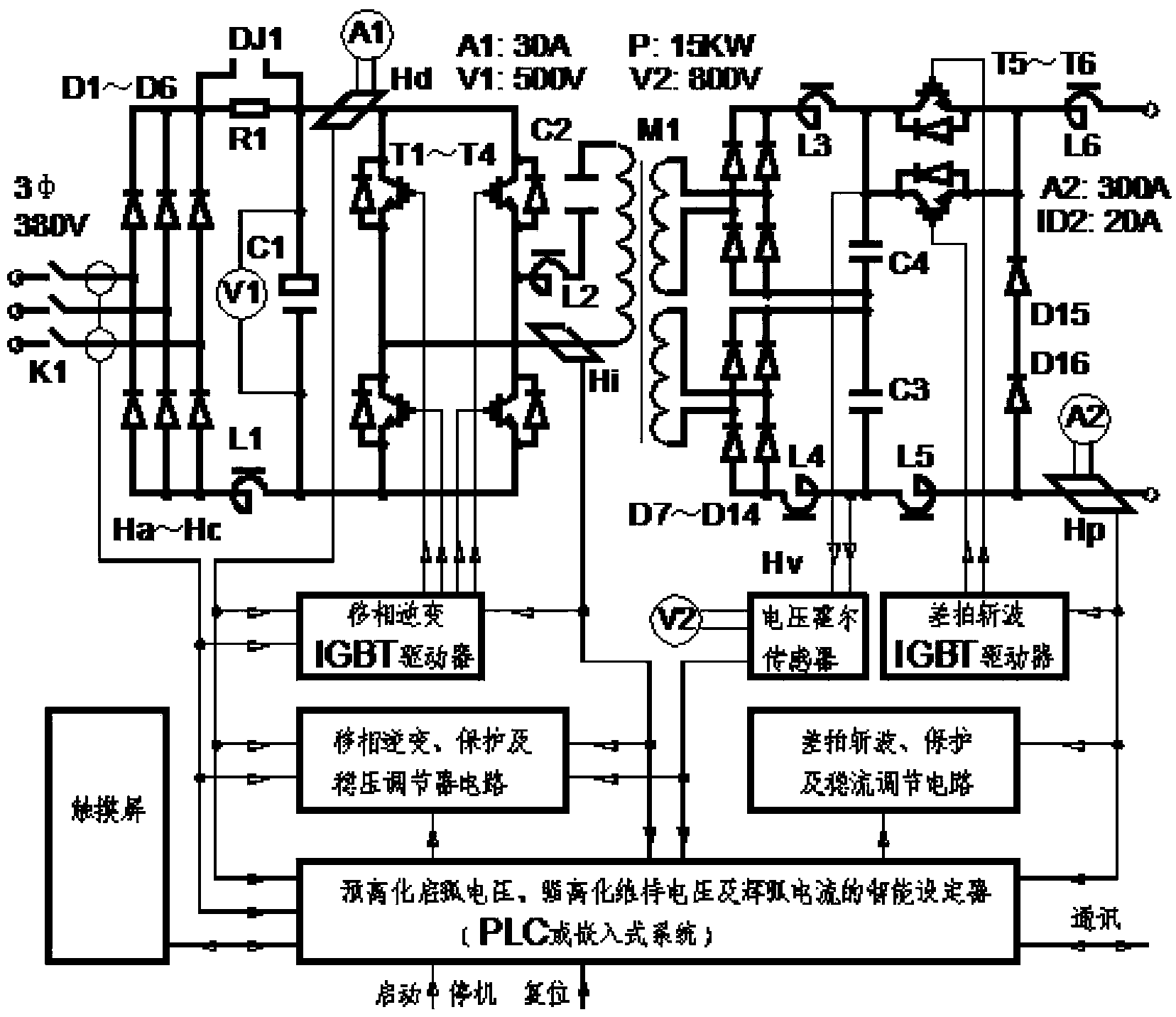

Image

  • Micro-arc ion plating method
  • Micro-arc ion plating method

Examples


Embodiment 1

[0022] CrN film was plated on the surface of M2 high-speed steel sample by micro-arc ion plating method, and it was implemented according to the following steps:

[0023] Step 1. Clean and dry the M2 high-speed steel sample and put it into the vacuum chamber, and vacuum the vacuum chamber to 6×10 -5 Argon gas is introduced at Pa, and the vacuum degree is kept at 0.6Pa;

[0024] Step 2. Turn on the pulsed Cr target power supply and the pulsed negative bias power supply to clean the sample by ion bombardment. The control parameters are: the pulsed Cr target voltage is -900V, the pulse width is 10μs, and the frequency is 2KHz; the pulsed negative bias voltage is -500V, and the pulse width is 2μs, frequency 150KHz. The ion cleaning time is 10min.

[0025] Step 3, depositing the Cr bottom layer, the control parameters are: pulsed Cr target voltage of -1000V, pulse width of 10μs, frequency of 10KHz; pulse negative bias voltage of -60V, pulse width of 0.5μs, frequency of 250KHz. L...

Embodiment 2

[0032] The surface of WC-Co cemented carbide samples was plated (Cr 0.45 Al 0.55 ) N film, implemented according to the following steps:

[0033] Step 1. Clean and dry the WC-Co cemented carbide sample and put it into the vacuum chamber, and vacuum the vacuum chamber to 6×10 -4At Pa, turn on the temperature control system to heat and control the temperature in the vacuum chamber at 300°C.

[0034] Step 2. Introduce argon gas to keep the vacuum at 0.4Pa;

[0035] Step 3. Turn on the pulse Cr 80 Al 20 The target power supply and the pulse negative bias power supply perform ion bombardment cleaning on the sample, and the control parameters are: pulse Cr 80 Al 20 The target voltage is -1000V, the pulse width is 3μs, and the frequency is 2.5KHz; the pulse negative bias is -400V, the pulse width is 2.5μs, and the frequency is 100KHz. The ion cleaning time is 3min.

[0036] Step 4: Enter N 2 Gas and keep the vacuum at 1.5Pa, start plating (Cr 0.45 Al 0.55 ) N layers. Turn...

Embodiment 3

[0042] Cr-C-N film was plated on the mirror-polished 304 stainless steel sample surface by micro-arc ion plating method, and implemented according to the following steps:

[0043] Step 1. Clean and dry the 304 stainless steel sample and put it into the vacuum chamber, and vacuum the vacuum chamber to 1×10 -4 Argon gas is introduced at Pa, and the vacuum degree is kept at 0.2Pa;

[0044] Step 2. Turn on the pulsed Cr target power supply and the pulsed negative bias power supply to clean the sample by ion bombardment. The control parameters are: pulse target voltage is -950V, pulse width is 12μs, frequency is 5KHz; pulse negative bias voltage is -550V, pulse width is 1.5 μs, frequency 50KHz. The ion cleaning time is 7min.

[0045] Step 3, depositing the Cr bottom layer, the control parameters are: pulsed Cr target voltage of -1200V, pulse width of 10μs, frequency of 10KHz; pulse negative bias voltage of -50V, pulse width of 1.5μs, frequency of 50KHz. last for 4min.

[0046] ...


PUM

PropertyMeasurementUnit
thicknessaaaaaaaaaa
surface roughnessaaaaaaaaaa
hardnessaaaaaaaaaa

Abstract

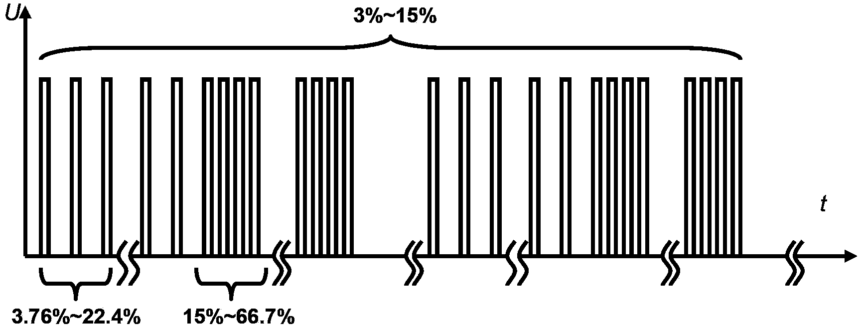
The invention discloses a vacuum plating method integrating advantages of magnetron sputtering and multiple-arc ion plating, in particular to a micro-arc ion plating method. The method comprises the steps as follows: a high-frequency impulse electric field with negative 1,200 V to negative 900 V output voltage, 0.5 KHz-60 KHz frequency and 0.5 mu s-30 mu s pulse width is firstly established, a high-frequency impulse signal output from the high-frequency impulse electric field is modulated by an adjustable inductance attenuation and a digital logic circuit and loaded to a rectangular cathode target with an area of 300 mm*100 mm and two ends of an anode vacuum chamber casing with a volume of Phi 450 mm *H 400 mm, and argon (Ar) gas charged into a vacuum chamber is subjected to an ion plating process when volt-ampere characteristics of negative 900 V to negative 600 V voltage, 100 A-300 A current, 1 ms-5 ms pulse width and 3%-15% duty ratio are generated during discharge. The method is simple and stable; and by means of the method, the yield is high, and industrial production can be realized.

Description

technical field [0001] The invention belongs to the technical field of material manufacturing, and specifically relates to a vacuum coating method which combines the advantages of compact and smooth magnetron sputtering film layer, fast deposition rate of multi-arc ion plating and good plating performance, referred to as micro-arc ion plating method. technical background [0002] Magnetron sputtering and multi-arc ion plating are the current mainstream PVD vacuum coating technologies, both of which have their own strengths and weaknesses. Magnetron sputtering with high-voltage and low-current characteristics has the advantages of low deposition temperature, dense and smooth film surface, and precise composition ratio. The shape and large size of the workpiece surface can obtain a film layer with uniform thickness, so a complex multi-axis rotating mechanism in the cavity must be configured during coating, resulting in low production efficiency. The multi-arc ion plating with...

Claims


Application Information

Patent Timeline
Patent Type & Authority Applications(China)
IPC IPC(8): C23C14/35
Inventor 蒋百铃曹政李洪涛赵健
Owner NANJING HAORANG ENVIRONMENT SCI & TECH
Learn More