


Quick Research
Generate reliable direction feasibility study reports for your R&D in just a few steps.

Technical Q&A
Discover and master advanced knowledge NOW. Basics, ideas, possibilities, all at once.

Find Solutions
As an expert in R&D theories, this can generate solutions to your technical problems instantly.

Evaluate Feasibility
Analyze your overall solution with one click, know your potential R&D risks in advance.

Monitor Landscape
Get weekly tech updates, stay abreast of the latest tech innovations and key insights.
Insulation apparatus for glass tank furnace
A heat preservation device and a glass tank kiln technology, applied in glass furnace equipment, glass manufacturing equipment, manufacturing tools, etc., can solve the problems of slender heat conduction path, less solid content, and lower solid heat conduction rate
- Summary
- Abstract
- Description
- Claims
- Application Information
AI Technical Summary
Problems solved by technology
Method used
Image


Examples
Embodiment 1)
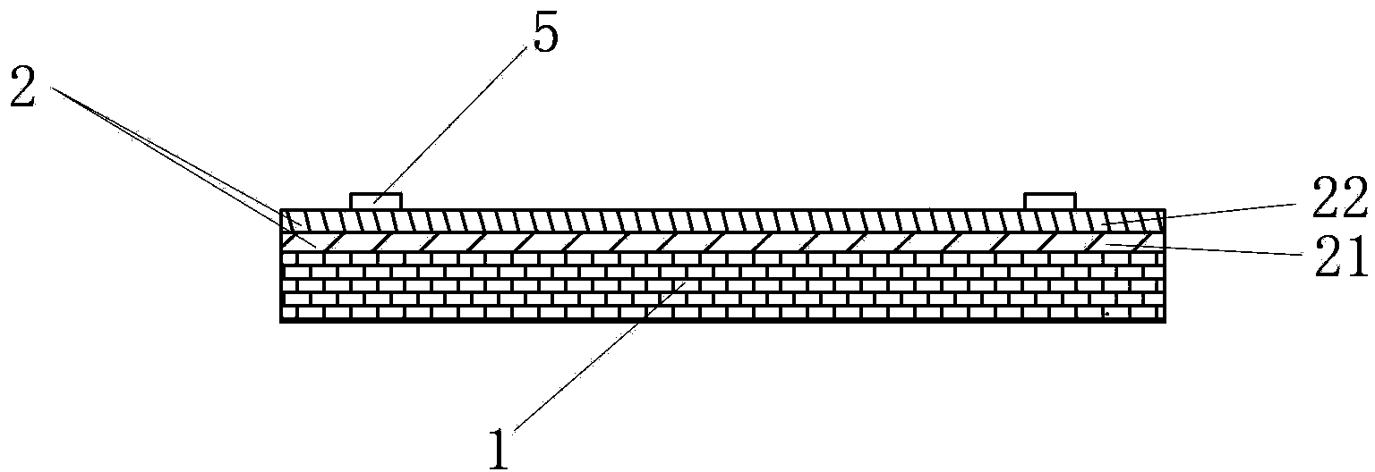
[0051] See figure 1 with figure 2 , The thermal insulation device of the glass tank kiln of this embodiment is the thermal insulation device of the float glass tank kiln, including the thermal insulation composite layer 2 and the fixing member 5 . The thermal insulation composite layer 2 is composed of an aluminum silicate fiber blanket layer 21 and a first airgel thermal insulation blanket layer 22 .
[0052] The aluminum silicate fiber blanket layer 21 and the first airgel thermal insulation blanket layer 22 are sequentially laid and covered on the outer surfaces of all parts of the glass tank kiln where the thermal insulation layer 1 is provided in the order from the inside to the outside, and the fixing member 5 is arranged on the first Outside the airgel thermal insulation blanket layer 22, the thermal insulation composite layer 2 is compacted and compacted on the outer surface of the thermal insulation layer 1 of the glass tank kiln. The thermal insulation layer 1 is ...
Embodiment 2)
[0061] See image 3 , The rest of this embodiment is the same as that of Embodiment 1, except that: the heat preservation device of the glass tank kiln of this embodiment also includes a reflective layer 4 . The reflective layer 4 is an aluminum plate or galvanized iron sheet with a thickness of 0.5 mm, covering the outer surface of the first airgel insulation blanket layer 22 of the thermal insulation composite layer 2, and the fixing part 5 is arranged outside the reflective layer 4, so that the reflective layer 4 and The thermal insulation composite layer 2 is pressed sequentially from the outside to the inside, and is compacted on the outer surface of the thermal insulation layer 1 of the glass tank kiln.
[0062] Compared with the heat preservation device of embodiment 1, the heat preservation device of this embodiment can reflect a part of the heat radiated from the heat preservation layer 1 of the glass tank kiln back to the heat preservation layer 1 due to the existenc...
Embodiment 3)
[0064] See Figure 4 with Figure 5 , the rest of this embodiment is the same as that of Embodiment 1, except that: the thermal insulation device of this embodiment also includes a thermal insulation composite layer 3 . The thermal insulation composite layer 3 is divided into a single thermal insulation composite layer 3a and a double thermal insulation composite layer 3b according to the number of glass fiber felt layers and airgel thermal insulation blanket layers included. The single thermal insulation composite layer 3a has only one composite layer, that is, the first glass fiber felt layer 31 and the second airgel thermal insulation blanket layer 32 are arranged sequentially from inside to outside. The double thermal insulation composite layer 3b has 2 composite layers, that is, the first glass fiber blanket layer 31, the second airgel thermal insulation blanket layer 32, the second glass fiber blanket layer 33 and the third airgel thermal insulation blanket layer 34 acc...
PUM
| Property | Measurement | Unit |
|---|---|---|
| thickness | aaaaa | aaaaa |
| thickness | aaaaa | aaaaa |
| thickness | aaaaa | aaaaa |
Abstract
Description
Claims
Application Information
 - R&D Engineer
- R&D Manager
- IP Professional
- Industry Leading Data Capabilities
- Powerful AI technology
- Patent DNA Extraction
Browse by: Latest US Patents, China's latest patents, Technical Efficacy Thesaurus, Application Domain, Technology Topic, Popular Technical Reports.
© 2024 PatSnap. All rights reserved.Legal|Privacy policy|Modern Slavery Act Transparency Statement|Sitemap|About US| Contact US: help@patsnap.com