
Manufacturing method of multi-gate field effect transistor fin structure

A technology for field effect transistors and manufacturing methods, applied in semiconductor/solid-state device manufacturing, electrical components, circuits, etc., can solve the problems of device drive current influence, channel mobility reduction, etc., and achieve the effect of simple process

Active Publication Date: 2016-04-20
SEMICON MFG INT (SHANGHAI) CORP
View PDF4 Cites 0 Cited by
  • Summary
  • Abstract
  • Description
  • Claims
  • Application Information

AI Technical Summary

Problems solved by technology

For example, a fin structure with a higher vertical height provides higher drive current, and a fin structure with a smaller horizontal width can better suppress leakage current. However, due to the continuous shrinking of the size, the vertical height of the fin structure gradually decreases. , the mobility of the channel in the device will be reduced, and the driving current of the device will be affected

Method used


Image

  • Manufacturing method of multi-gate field effect transistor fin structure
  • Manufacturing method of multi-gate field effect transistor fin structure
  • Manufacturing method of multi-gate field effect transistor fin structure

Examples


Embodiment Construction

[0023] In order to make the content of the present invention clearer and easier to understand, the content of the present invention will be further described below in conjunction with the accompanying drawings. Of course, the present invention is not limited to this specific embodiment, and general replacements known to those skilled in the art are also covered within the protection scope of the present invention.

[0024] Secondly, the present invention is described in detail by means of schematic diagrams. When describing the examples of the present invention in detail, for the convenience of explanation, the schematic diagrams are not partially enlarged according to the general scale, which should not be used as a limitation of the present invention.

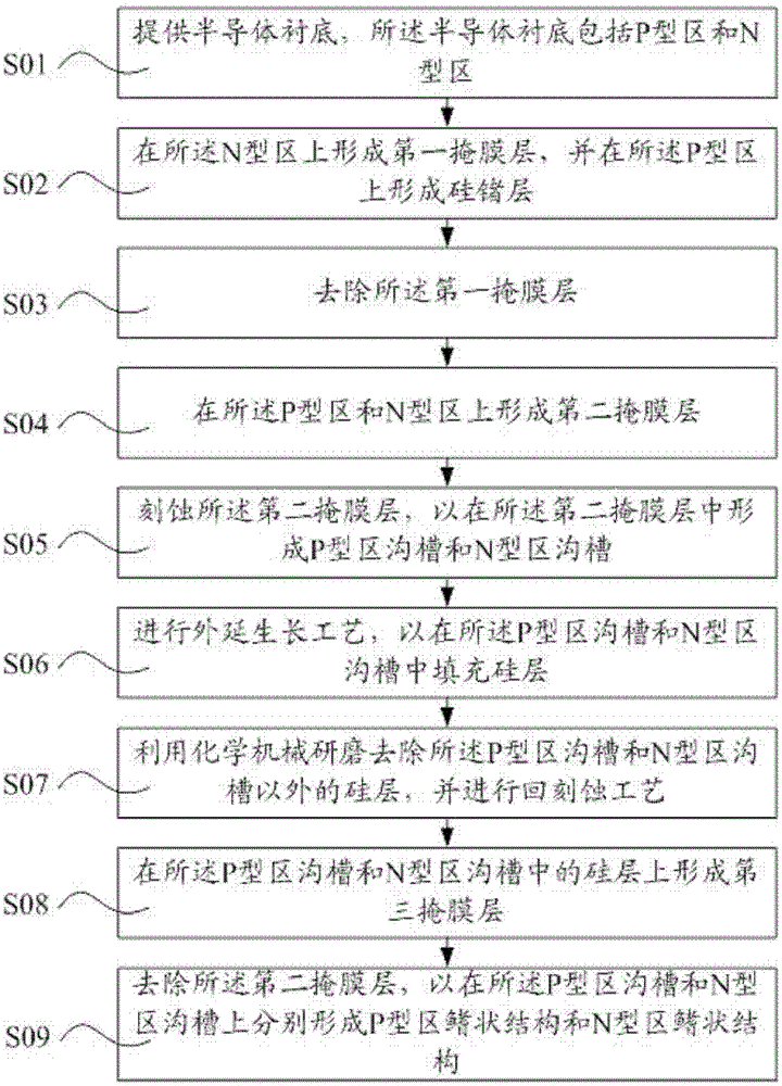
[0025] figure 1 It is a schematic flow chart of the manufacturing method of the multi-gate field effect transistor fin structure in an embodiment of the present invention. The invention provides a method for manufacturing a ...


PUM


Abstract

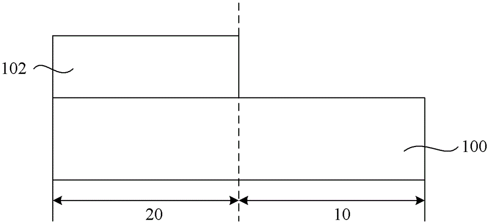
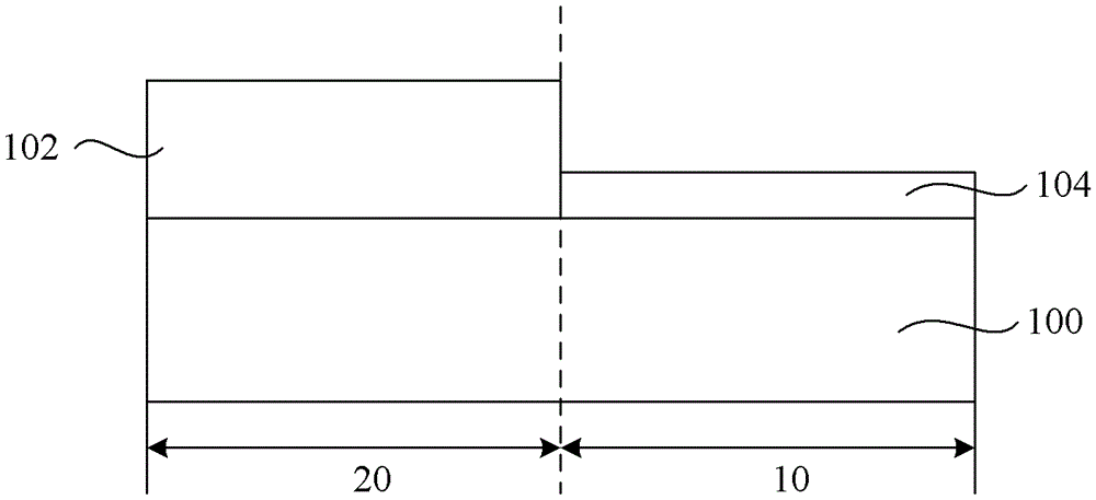
The invention provides a method for manufacturing fin-shaped structures of a multi-gate field effect transistor. The method comprises the steps: providing a semiconductor substrate, wherein the semiconductor substrate comprises a P-type area and an N-type area; forming a first mask layer on the N-type area, and forming a silicon-germanium layer on the semiconductor substrate; removing the first mask layer; forming second mask layers on the P-type area and the N-type area; etching the second mask layers so as to form a P-type area groove and an N-type area groove; filling the P-type area groove and the N-type area groove with silicon layers; removing the silicon layers outside the P-type area groove and the N-type area groove, and performing an etching-back process; forming third mask layers in the P-type area groove and the N-type area groove; removing the second mask layers so as to form a P-type area fin-shaped structure and an N-type area fin-shaped structure. Due to the fact that the P-type area fin-shaped structure and the N-type area fin-shaped structure are formed on the P-type area and the N-type area respectively, the P-type area fin-shaped structure and the N-type area fin-shaped structure which are different in stress can be formed, the technique is simple, and manufacturing cost is lowered.

Description

technical field [0001] The invention relates to the field of integrated circuit manufacturing, in particular to a method for manufacturing a multi-gate field effect transistor fin structure. Background technique [0002] In recent years, metal-oxide-semiconductor field-effect transistors (MOSFETs) have continued to shrink in size. This is to increase speed, improve component integration and reduce the cost of integrated circuits. The size of transistors continues to decrease, and the reduction of transistors has reached limit of various performances. The thickness of the gate oxide and the depth of the source / drain junction have reached their limits. [0003] Therefore, the industry has developed a multi-gate field effect transistor (Multi-Gate Transistors), and the multi-gate field effect transistor technology is a new circuit structure technology. Traditional transistors have only one gate for each transistor to control the passage or interruption of current between two ...

Claims


Application Information

Patent Timeline
Patent Type & Authority Patents(China)
IPC IPC(8): H01L21/8238
Inventor 鲍宇
Owner SEMICON MFG INT (SHANGHAI) CORP
Learn More