Laser processing method and system assisted by water jet and gas jet

An auxiliary laser and water jet technology, applied in laser welding equipment, metal processing equipment, manufacturing tools, etc., can solve the problem of ineffective removal of laser etching debris and cooling, affecting laser etching efficiency and processing quality, and inability to use Larger thickness plate cutting and other problems, to achieve the effect of improving efficiency and processing quality, eliminating thermal influence, and obvious superiority

Inactive Publication Date: 2013-10-23
GUILIN UNIV OF ELECTRONIC TECH +1
View PDF6 Cites 26 Cited by
  • Summary
  • Abstract
  • Description
  • Claims
  • Application Information

AI Technical Summary

Problems solved by technology

However, when the depth of laser etching process is increased, the amount of air flow of the gas nozzle entering the cutting seam is significantly reduced, thus greatly reducing the efficiency of the gas nozzle, and cannot effectively remove the debris generated by laser etching and cool down. Directly affect the laser etching efficiency and processing quality, for example, the workpiece will produce recast layer, residual stress and micro cracks, etc.
Therefore, the current laser processing kerf depth is less than 10mm, which cannot be used for cutting larger thickness plates

Method used


Image

  • Laser processing method and system assisted by water jet and gas jet
  • Laser processing method and system assisted by water jet and gas jet

Examples


Embodiment Construction

[0027] Method embodiment of water jet and airflow composite assisted laser processing

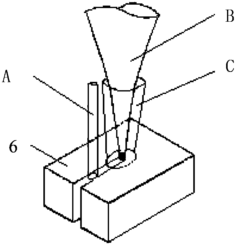
[0028] The principle diagram of the embodiment of the method of water jet and airflow composite assisted laser processing is as follows figure 1 as shown,

[0029] The laser beam B is focused on the surface of the workpiece, the air beam C is coaxial with the laser beam B, and both are perpendicular to the surface of the workpiece, the diameter of the air beam C is larger than the diameter of the focus point of the laser beam B, and there is a water jet A behind the air beam C, and the water jet The beam A is also perpendicular to the surface of the workpiece and enters the kerf of the laser processed workpiece 6 .

[0030] The water of the water jet in this example is deionized water, distilled water can also be used.

[0031] In this example, the distance between the intersection point of the center line of the water jet beam and the surface of the workpiece and the center of the focal ...


PUM


Abstract

The invention discloses a laser processing method and system assisted by a water jet and a gas jet. According to the laser processing method, a laser beam is focused on the surface of a workpiece; a gas jet beam of which the diameter is greater than that of the focus point of the laser beam is coaxial with the laser beam; after the gas jet beam enters a cut slot, a water jet beam behind the gas jet beam also enters the cut slot. The center line of the water jet beam is in a plane formed by the center line of the laser beam and the cut slot; the intersection point of the center line of the water jet beam and the surface of the workpiece is 1-2 mm from the focus point of the laser beam. The system comprises a laser generating mechanism, a gas jet nozzle and a workbench, wherein the longitudinal center line of the jet hole of a water jet nozzle behind the gas jet nozzle is in the plane formed by the center line of the laser beam and the cut slot; a gas pump and a water pump are respectively connected with the gas jet nozzle and the water jet nozzle; water circulates through the water pump, the water jet nozzle, a working cavity above the workbench and a water tank. According to the invention, the water jet beam restrains gas expansion, reduces the heat effect of laser, takes away deposits, and improves the efficiency and quality of laser ablation, so that the invention achieves remarkable effects particularly in processing plates with thicknesses above 15 mm.

Description

technical field [0001] The invention belongs to the technical field of laser processing, and in particular relates to a water jet and airflow compound-assisted laser processing method and system for improving laser processing efficiency. Background technique [0002] Laser processing is suitable for most materials and has the advantages of non-contact, flexibility and precision. However, for some applications in the field of micron and submicron etching, the heat-affected zone, deposition and impact damage effects caused by laser direct etching cannot be ignored. For this reason, in the current laser processing, the auxiliary gas injection is used to blow away the spatter generated by the laser direct engraving, and at the same time reduce the temperature of the laser processing area. However, when the depth of laser etching process is increased, the amount of air flow of the gas nozzle entering the cutting seam is significantly reduced, thus greatly reducing the efficiency...

Claims


Application Information

Patent Timeline
IPC IPC(8): B23K26/36B23K26/14
Inventor 龙芋宏邹登峰廖志强江威
Owner GUILIN UNIV OF ELECTRONIC TECH
Why Eureka
Try Eureka