Vehicle control device and control method

A vehicle control device and vehicle technology, applied in the direction of transmission control, non-mechanical drive clutches, components with teeth, etc., can solve the problems of tooth-tip dog-tooth clutches that cannot be engaged, and achieve the goal of suppressing fuel consumption and fast power transmission Effect

Active Publication Date: 2017-05-31
TOYOTA JIDOSHA KK
View PDF7 Cites 0 Cited by
  • Summary
  • Abstract
  • Description
  • Claims
  • Application Information

AI Technical Summary

Problems solved by technology

Due to the phase shift between the engaging tooth and the engaged tooth, the tooth tips contact each other, and when the sleeve moves to the engaging side with the shifted phase, there is a tooth tip contacting each other and the dog clutch cannot be engaged (i.e. , the possibility of engagement failure of the so-called up-lock

Method used


Image

  • Vehicle control device and control method
  • Vehicle control device and control method
  • Vehicle control device and control method

Examples


Embodiment Construction

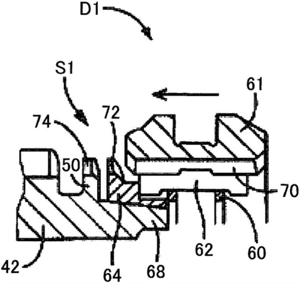
[0024] In the present invention, locking preferably corresponds to Figure 5 The state shown, in which the tips of the spline teeth 70 (61) formed in the sleeve constituting the synchromesh mechanism are in contact with the tips of the spline teeth 72 (64) formed in the synchronizer ring, and the canine teeth clutch D1 cannot be engaged.

[0025] Hereinafter, embodiments of the present invention will be described in detail with reference to the accompanying drawings. It should be noted that in the following embodiments, the drawings are simplified or deformed as necessary, and parts are not necessarily drawn precisely in terms of dimensional ratios, shapes, and the like.

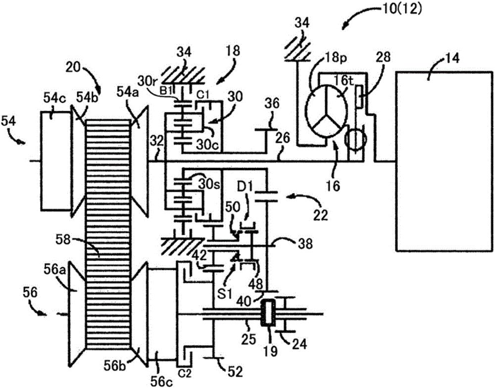
[0026] figure 1 is a schematic diagram for explaining a schematic configuration of a drive device 12 provided in a vehicle 10 as an embodiment of the present invention. The driving device 12 includes an engine 14 serving as a driving force source of, for example, a vehicle, a torque converter 16 as a flui...


PUM


Abstract

In a control device for a vehicle including: a dog clutch mechanism that is disposed in a power transmission path in which a driving force is transmitted from an engine to a wheel and is operated by a hydraulic actuator; and an electric oil pump that supplies hydraulic pressure to the hydraulic actuator, rotation of the engine is stopped in a state in which the dog clutch mechanism is engaged by the hydraulic pressure supplied from the electric oil pump at a time during an engine stop operation, the rotation of the engine is started in the state in which the dog clutch mechanism is engaged by the hydraulic pressure supplied from the electric oil pump at a time during an engine restart operation, hence occurrence of up-lock of the dog clutch mechanism is prevented.

Description

technical field [0001] The present invention relates to a vehicle control device and a control method, and in particular to a vehicle control device and a control method including a dog clutch mechanism. Background technique [0002] There is a transmission that puts each pair of gears into a power transmission state or a non-power transmission state to obtain a desired speed ratio by operating a dog clutch mechanism using a hydraulic actuator. For example, Japanese Patent Application Publication No. 2008-202684 (JP 2008-202684A) employs a clutch that uses a dog clutch mechanism and an actuator that controls the dog clutch mechanism to automatically perform the transmission between the above-mentioned transmissions such as Engagement operation for connection between driving power sources such as an engine. [0003] For example, in a vehicle including a dog clutch mechanism described in JP 2008-202684A, the dog clutch mechanism is engaged by supplying hydraulic pressure from...

Claims


Application Information

Patent Timeline
Patent Type & Authority Applications(China)
IPC IPC(8): F16H61/28F16H61/00
CPCF16H2061/047F16H61/2807F16H61/0031B60W10/02B60W10/06B60W10/30B60W30/18018B60W2510/0208B60W2510/0638B60W2510/1005B60W2510/30B60W2710/021B60W2710/06B60W2710/30F16D25/061F16D25/14F16D2048/0233F16D2048/0245
Inventor 松尾贤治日野顕近藤宏纪深尾光博井上大辅绫部笃史二谷啓允坂本和也
Owner TOYOTA JIDOSHA KK
Why Eureka
Try Eureka