
Apparatus to enable a user to simulate skating

a technology of skating apparatus and user, applied in the field of skating apparatus, can solve the problem that the prior art skating machine suffers from one critical design d

Active Publication Date: 2009-01-06
HUPA INTERNATIONAL INC
View PDF3 Cites 26 Cited by
  • Summary
  • Abstract
  • Description
  • Claims
  • Application Information

AI Technical Summary

Benefits of technology

[0008]With the aid of all the flexible parts, during operation, the flexible parts prevents the skating machine from locking or freezing at two positions, where the pedals are at their extreme left or right position so that the crank and pedal connector flexible bars are aligned with each other which causes locking and freezing of the circular motion of the upper part of the machine.
[0014]It is also an object of the present invention to provide a skating machine which will not lock and will provide a mostly smooth skating action through the addition of flexible structural parts including an identical first and second pedal connector flex bar, a resilient tension means and at least one transverse interconnecting elastic means.

Problems solved by technology

However, prior art skating machines suffer from one critical design defect.

Method used


Image

  • Apparatus to enable a user to simulate skating
  • Apparatus to enable a user to simulate skating
  • Apparatus to enable a user to simulate skating

Examples


Embodiment Construction

[0050]Although specific embodiments of the present invention will now be described with reference to the drawings, it should be understood that such embodiments are by way of example only and merely illustrative of but a small number of the many possible specific embodiments which can represent applications of the principles of the present invention. Various changes and modifications obvious to one skilled in the art to which the present invention pertains are deemed to be within the spirit, scope and contemplation of the present invention as further defined in the appended claims.

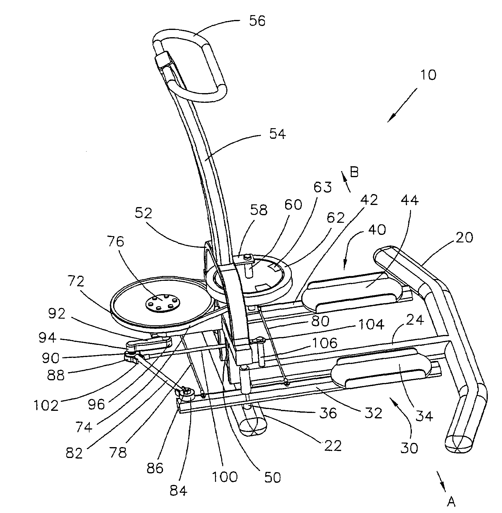
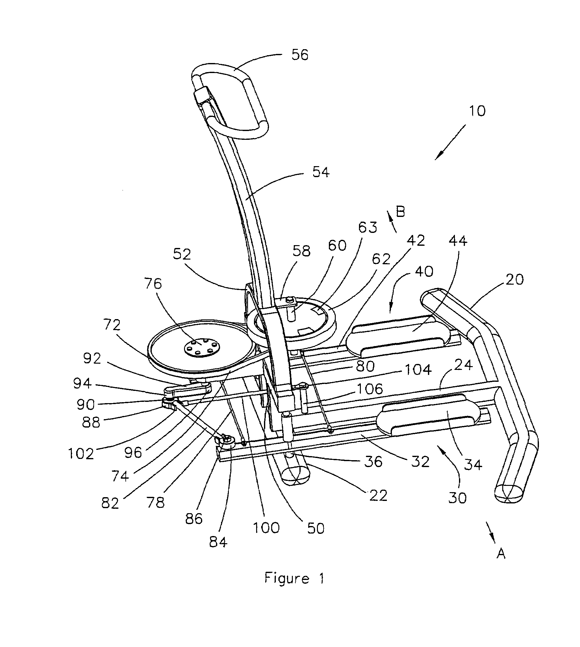
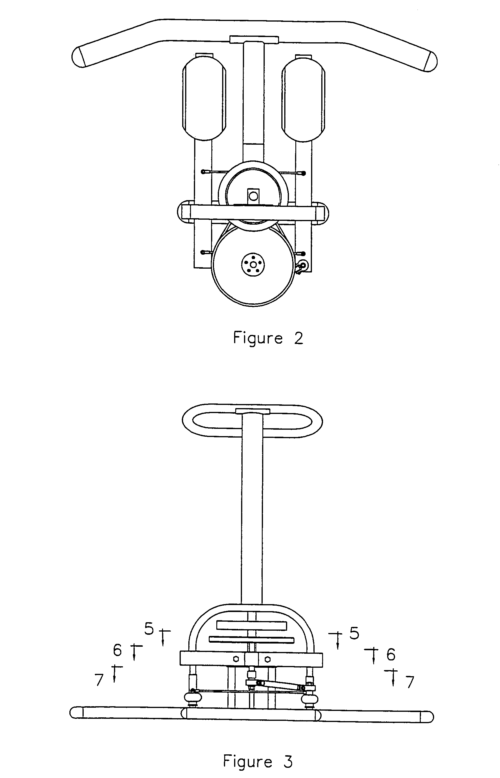
[0051]Referring to FIGS. 1 through 13, there is illustrated the preferred embodiment of the present invention apparatus to enable a user to simulate skating which will hereinafter be referred to as a skating machine 10. The skating machine 10 is supported on a rear transverse frame 20, and a front transverse frame 22 which are interconnected by a longitudinal frame 24. The skating machine 10 further compri...


PUM


Abstract

An improved skating machine, wherein the improvement involves the incorporation of flexible components including (1) identical first and second pedal connector flexible bars rotatably connected at one respective one to a respective first and second longitudinal pedal bar and rotatably connected at their respective opposite end to a crank axle; (2) a resilient tension means connected at one end to the crank axle and connected at its opposite end to a post which is attached to a portion of a central longitudinal base frame; and (3) at least one transverse interconnecting elastic means transversely interconnecting the first and second longitudinal pedal bars. The flexible components have sufficient elasticity to prevent the machine from locking when the crank and the pedal connector bars are aligned with each other when the pedals are at their extreme left or right position.

Description

[0001]The present application is a continuation-in-part of a patent application Ser. No. 11 / 082,279 filed on Mar. 16, 2005 now U.S. Pat. No. 7,338,414.BACKGROUND OF THE INVENTION[0002]1. Field of the Invention[0003]The present invention relates to exercise apparatus, and more particularly to a specific type of exercise apparatus which enables a user to simulate skating.[0004]2. Description of the Prior Art[0005]In general, apparatus which enables a user to simulate skating, known as a skating machine, has been known in the prior art. However, prior art skating machines suffer from one critical design defect. In prior art skating machines, the apparatus by which the skating foot pedal moves side to side is a double crank apparatus which is not restrained in any manner in the longitudinal direction. As a result, the double crank can be rotated to a point where the two cranks are at 180 degrees to each other which creates a “dead” angle so that the two cranks lock in place and the skat...

Claims


Application Information

Patent Timeline
Patent Type & Authority Patents(United States)
IPC IPC(8): A63B21/00
CPCA63B21/154A63B22/0061A63B69/0022A63B21/225A63B2022/0033
Inventor HSIUNG, BOB
Owner HUPA INTERNATIONAL INC
Learn More