
A finish-milling high-precision guide-surface welding type cemented carbide spiral end mill

A technology of cemented carbide and end mills, applied in the field of machining metal cutting

Active Publication Date: 2013-10-23
江苏苏铃精工机械有限公司
View PDF5 Cites 3 Cited by
  • Summary
  • Abstract
  • Description
  • Claims
  • Application Information

AI Technical Summary

Problems solved by technology

In order to ensure such high precision, many companies choose high-precision parent machines to process the guide rail surface, such as Dawei, Mazak, Workman, etc., and the processing tools use imported carbide end mills or imported machine clamping indexable end mills For cutting, the tool price is expensive, but the quality of the processed guide rail fluctuates greatly, and it is often corrected by manual shoveling or repaired on a gantry grinder
There are also enterprises that try to use domestic carbide helical end mills to process the guide rail surface, but the accuracy cannot be achieved at all. It is difficult to process two bed beds with one milling cutter, and it is necessary to perform program interpolation processing. Therefore, some large and medium-sized machine tool factories, Directly grind the guide rail surface on the CNC gantry guide rail grinder, the processing cost is higher, and the efficiency is also low. The fine milling and high-precision guide rail surface has become the bottleneck of many enterprises.

Method used


Image

  • A finish-milling high-precision guide-surface welding type cemented carbide spiral end mill
  • A finish-milling high-precision guide-surface welding type cemented carbide spiral end mill
  • A finish-milling high-precision guide-surface welding type cemented carbide spiral end mill

Examples


Embodiment Construction

[0026] The present invention will be further described below in conjunction with the accompanying drawings.

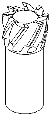
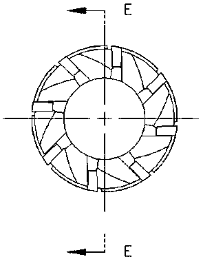
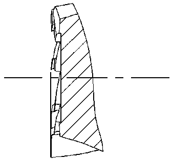
[0027] like Figure 1-Figure 4 Shown, a kind of fine milling high-precision guide rail surface welding type cemented carbide spiral end mill, the fine milling guide rail surface cemented carbide spiral end mill of the present invention has a cutter body and several hard alloys welded on the cutter body Composed of alloy spiral blades, the cutter body is made of 9crsi alloy steel, and the blade material is YL10.2. The simple production process is: cutting, turning, milling, quenching HRC56-60, welding and grinding the center hole, external grinding, CNC five-axis linkage tool grinding, open side cutting edge and end face cutting edge and fine grinding of the tip arc.

[0028] In order to ensure that the reference runout of the side blade and the end face blade to the handle is less than 0.008mm, it is required that the precision of the chuck holding the handle of the C...


PUM


Abstract

The invention discloses a finish-milling high-precision guide-surface welding type cemented carbide spiral end mill. The end mill has a tooth number of 8-10 and is thick-teeth type. Adjacent blade angles are 36-45 degrees. Helix angles of adjacent blades of side blades are different, and are 35 degrees and 30 degrees respectively. The end mill is especially suitable for finish-milling four items, namely a lathe bed, a column, a carriage, a horizontal bearing-surface and a side bearing-surface, of a machine, wherein the horizontal bearing-surface and the side bearing-surface are used in a workbench for placing a precision linear rail. The end mill is also suitable for finish-milling a plane surface and a step surface, and is a cemented carbide spiral end mill belonging to finish machining and semi-finish machining numerical control. The end mill employs a new material as the material of the cemented carbide blade and geometrical parameters of the end mill blade change greatly. The horizontal bearing-surface and the side bearing-surface machined by the end mill have high precision, and meet drawing precision completely without needs of spading, scraping or finish grinding. The end mill has a long service lifetime and a low cost performance ratio. The price of the end mill is only one fourth of the price of import cutting tools. Machinability of the end mill is not worse than the same kind of import cutting tools having a brand of Japan OSG, SUMITOMO, etc..

Description

technical field [0001] The invention relates to a fine-milling high-precision guide rail surface welding type cemented carbide spiral end mill, which is a CNC numerical control tool and belongs to the field of machining metal cutting. Background technique [0002] The bed (base), column, carriage, workbench and other large parts of precision machine tools such as CNC machining center EDM wire cutting machine and EDM machine are equipped with very high-precision linear guide rails, and the positioning and fixed linear guide rails It is two mutually perpendicular, two sets of finishing surfaces, commonly known as side guide rail surface and flat guide rail surface, usually the guide rail surface is 1.2-2 meters long, the straightness of the two guide rails is required to be 0.005mm, and the mutual parallelism is 0.005-0.008mm, rough It is required to be Ra0.8-1.6mm, and the processing is very difficult, such as Figure 5 shown. In order to ensure such high precision, many com...

Claims


Application Information

Patent Timeline
Patent Type & Authority Applications(China)
IPC IPC(8): B23C5/10
Inventor 谈文钰田润科
Owner 江苏苏铃精工机械有限公司
Learn More