
Vertical pres-stressed anchor rod gravity-type composite retaining wall and method for designing and constructing retaining wall

A technology of vertical prestressing and composite retaining walls, which is applied to artificial islands, sheet pile walls, water conservancy projects, etc., can solve problems such as the stability of disturbed slopes, large space requirements for retaining walls, and difficulty in guaranteeing the design service life. Good effect of preventing slope disasters, reducing gravity and occupying area

Inactive Publication Date: 2013-10-16
QINGDAO TECHNOLOGICAL UNIVERSITY
View PDF8 Cites 14 Cited by
  • Summary
  • Abstract
  • Description
  • Claims
  • Application Information

AI Technical Summary

Problems solved by technology

The anchor retaining wall is composed of reinforced concrete walls and anchors. It relies on the anchors anchored in the rock to provide horizontal tension to resist the lateral pressure of the soil. The anchors are generally horizontally inclined downwards by 10°-15°, which is the main force. However, the anchor rod must be anchored in the stable bedrock under the sliding surface of the slope. The farther the anchor rod is from the bottom of the wall, the longer the material length is required, and the anchor rod material exposed inside the slope cannot guarantee its corrosion resistance. performance, and the design service life is also difficult to guarantee
[0006] It can be seen that the traditional retaining wall support and reinforcement structure requires a large space for retaining walls at the slope toe, or the construction operation is complicated and the project cost is high, or the slope stability is disturbed by additional cutting. Has its shortcomings, and has limitations for special venues

Method used


Image

  • Vertical pres-stressed anchor rod gravity-type composite retaining wall and method for designing and constructing retaining wall
  • Vertical pres-stressed anchor rod gravity-type composite retaining wall and method for designing and constructing retaining wall
  • Vertical pres-stressed anchor rod gravity-type composite retaining wall and method for designing and constructing retaining wall

Examples


Embodiment Construction

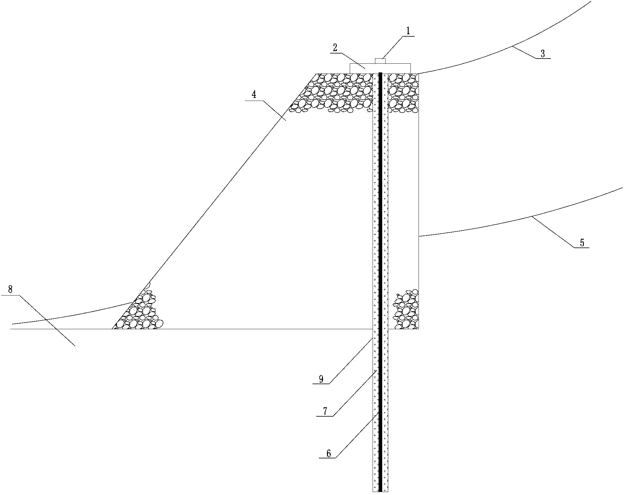
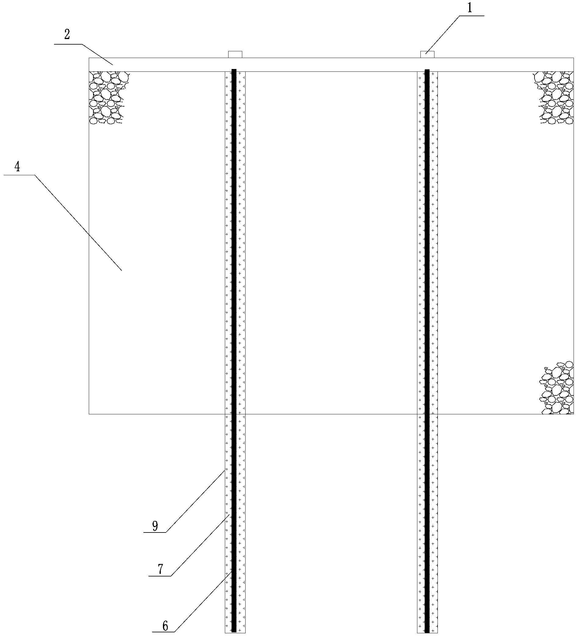
[0089] The vertical prestressed gravity composite retaining wall of the present invention includes a mortar block stone wall 4 arranged on the bedrock layer 8, and the mortar block stone wall 4 and the bedrock layer 8 are provided with anchor holes 9 along the same vertical direction. , the anchor hole 9 is provided with an anchor rod 6, cement mortar 7 is filled between the anchor rod 6 and the anchor hole 9, the top of the anchor hole 9 is provided with a concrete anchor beam 2, and the concrete anchor beam 2 is placed in the mortar block stone wall 4 The upper end of the concrete anchor beam 2 is provided with a concrete anchor head 1.

[0090] Anchor holes 9 are arranged at intervals along the road direction. The anchor rod adopts high-strength precision rail rebar, and the part of the anchor rod placed in the mortar block stone wall 4 is a free section, which is wrapped with two layers of asphalt fiberglass cloth, and the outside is wrapped with a diameter PVC pipe.

[0...


PUM


Abstract

The invention relates to the technical field of geotechnical engineering disaster prevention and control, in particular to a vertical pre-stress anchor rod gravity-type composite retaining wall which comprises a mortar building block stone wall arranged on a bed rock layer. Anchor holes are formed in the mortar building block stone wall and the bed rock layer in the vertical direction. An anchor rod is arranged inside each anchor hole. Cement mortar is filled between the anchor rod and the anchor holes. A concrete anchor beam is arranged at the top end of each anchor hole. The concrete anchor beams are arranged at the upper end of the mortar building block stone wall. A concrete anchor head is arranged on each concrete anchor beam. Compared with a traditional gravity-type retaining wall, the vertical pre-stress anchor rod gravity-type composite retaining wall has the advantages that elastic retraction of the anchor rods is utilized for applying pre-stressing force on the wall body, the weight of retaining wall masonry can be replaced, the sectional size of the retaining wall is reduced, and the integrality and the shearing strength of the wall body of the retaining wall are strengthened.

Description

technical field [0001] The invention relates to the technical field of disaster prevention and control in geotechnical engineering, and specifically relates to the establishment of a vertical prestressed anchor and gravity retaining wall for controlling unstable slopes by comprehensively utilizing the characteristics of anti-slump force of prestressed anchors and gravity retaining walls. The design method of the composite support structure of the wall and the construction method of the structure. Background technique [0002] Landslide is a kind of natural disaster with wide distribution and great harm. With the rapid development of economic construction, a large number of slope engineering stability problems will be encountered in engineering fields such as water conservancy and hydropower, railway, highway, and mine construction. Slope reinforcement has become a common difficult problem in infrastructure construction in my country. Therefore, , the slope support and retain...

Claims


Application Information

Patent Timeline
IPC IPC(8): E02D29/02E02D5/76
Inventor 贺可强于广明洪勇王凯杨德兵
Owner QINGDAO TECHNOLOGICAL UNIVERSITY
Learn More