Numerical control flat tube polisher and polishing line assembly with same

A technology of grinding machine and pneumatic grinding machine, which is applied to machine tools, grinding machines, grinding workpiece supports and other directions suitable for grinding workpiece planes, to achieve the effects of high use and promotion value, efficient grinding, easy control of work process and work accuracy

Active Publication Date: 2013-10-09
XUZHOU HUAHENG ROBOT SYST
View PDF6 Cites 4 Cited by
  • Summary
  • Abstract
  • Description
  • Claims
  • Application Information

AI Technical Summary

Problems solved by technology

However, in the prior art, there is no automatic equipment that can realize the above-mentioned grinding function efficiently and conveniently.

Method used


Image

  • Numerical control flat tube polisher and polishing line assembly with same
  • Numerical control flat tube polisher and polishing line assembly with same
  • Numerical control flat tube polisher and polishing line assembly with same

Examples


Embodiment 1

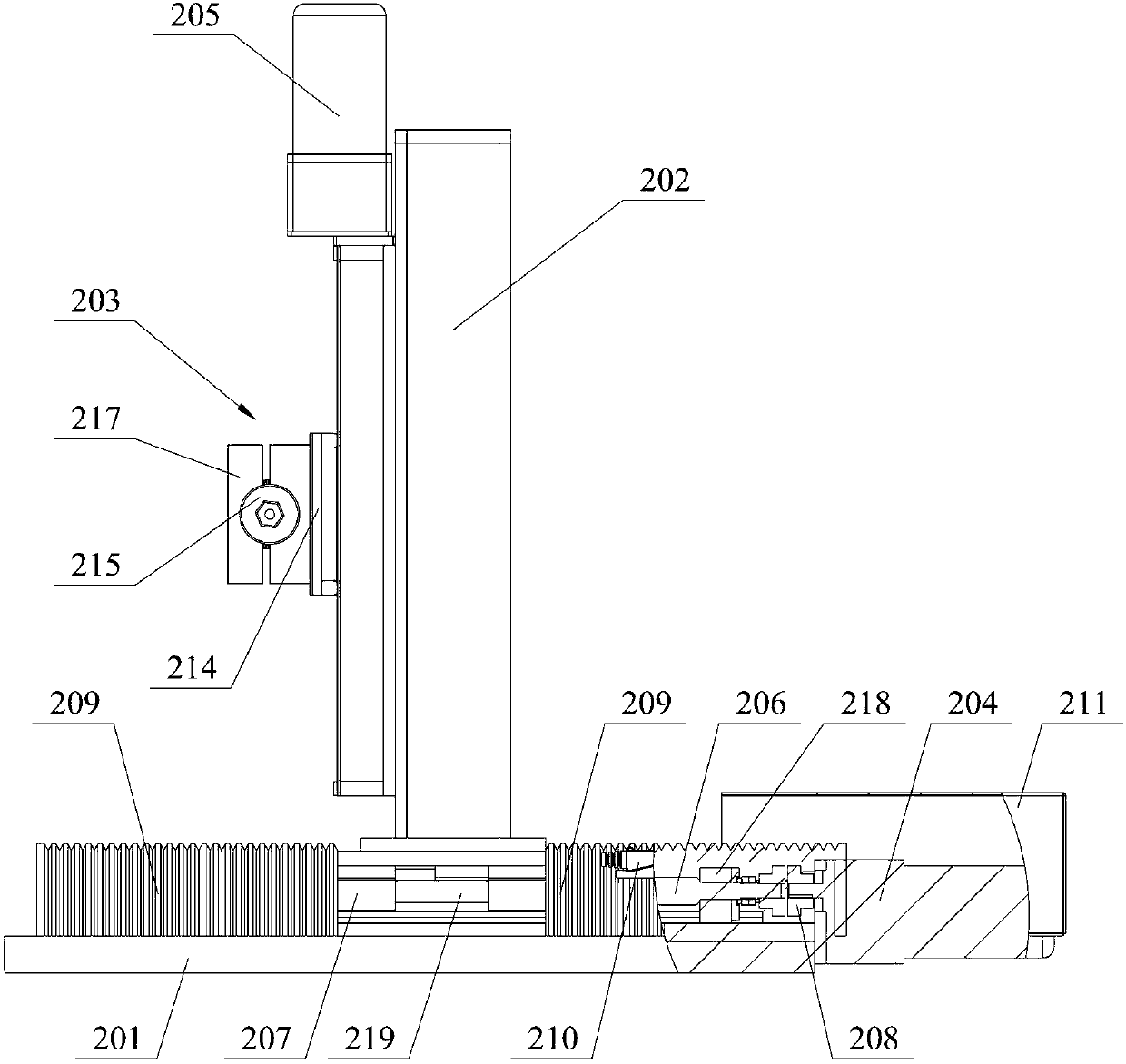
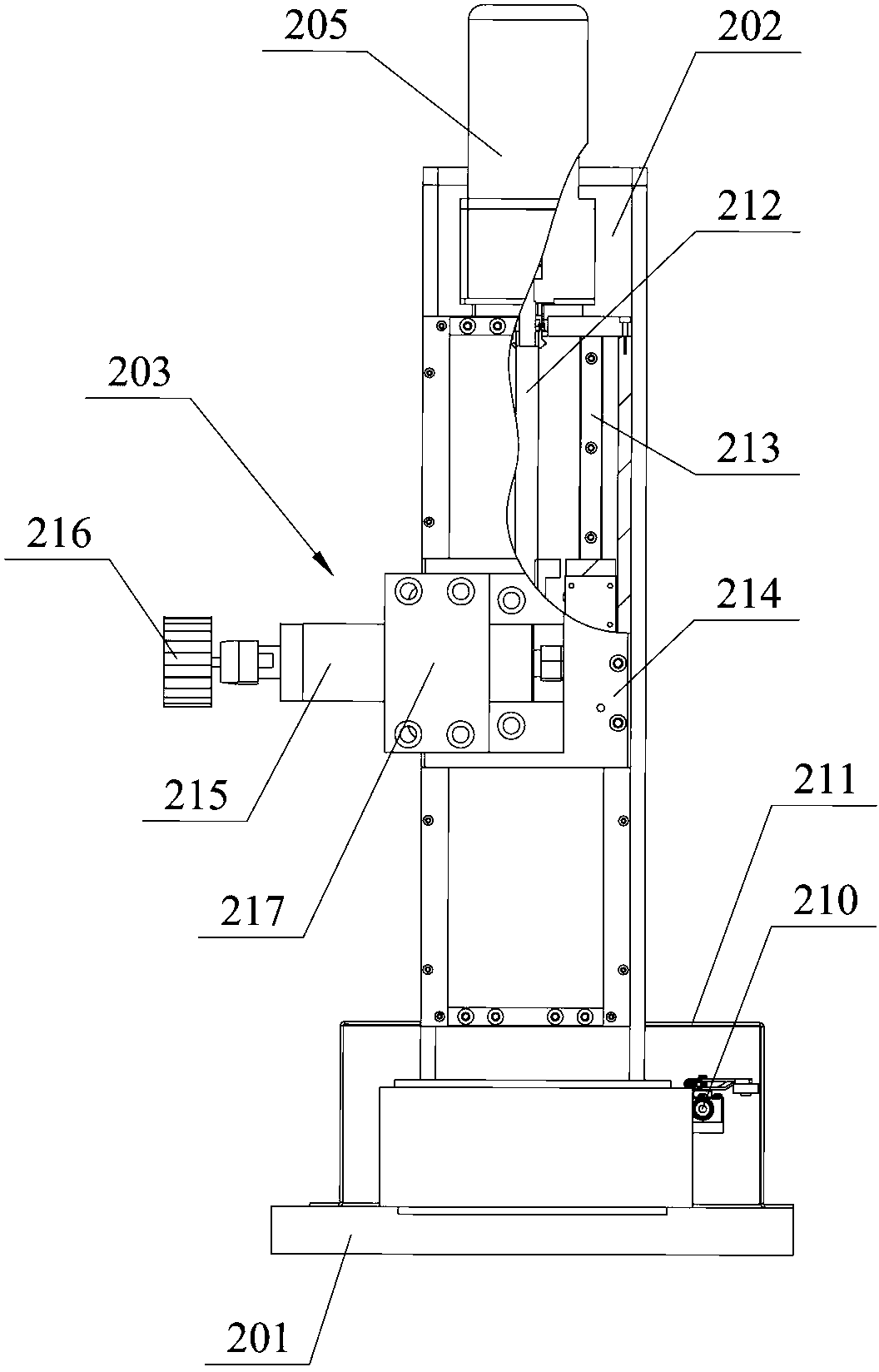
[0029] Embodiment one: see attached figure 1 to attach image 3 shown. A numerical control flat tube grinding machine 2 is used for grinding the end of the extended flat tube 1 in the radiator. The radiator usually has 20 flat tubes 1 welded by two heads. The length of the flat tube 1 is usually 12-9000mm, the width is usually 220mm, and the thickness is usually 20mm, and its surface is coated with galvanized layer. head to remove the galvanizing.

[0030] The numerically controlled flat tube grinding machine 2 includes a connection plate 201, a support beam 202 that is connected to the connection plate 201 by a horizontal movement mechanism and can move horizontally on the connection plate 201, and is connected to the support beam 202 by a vertical movement mechanism. A pneumatic grinder 203 that can move vertically on the support beam 202, a first drive mechanism 204 that drives the support beam 202 to move in the horizontal direction, a second drive mechanism 205 that d...


PUM


Abstract

The invention relates to a numerical control flat tube polisher which comprises a connecting plate, a supporting beam, a pneumatic polisher, a first driving mechanism, a second driving mechanism and a numerical control mechanism, wherein the supporting beam is connected to the connecting plate through a horizontal moving mechanism and can move on the connecting plate in a horizontal direction, the pneumatic polisher is connected to the supporting beam through a vertical moving mechanism and can move on the supporting beam in a vertical direction, the first driving mechanism drives the supporting beam to move in the horizontal direction, the second driving mechanism drives the pneumatic polisher to move in the vertical direction, and the numerical control mechanism controls the first driving mechanism and the second driving mechanism. The invention further relates to a polishing line assembly with the numerical control flat tube polishers. The polishing line assembly comprises a rack, a rolling wheel frame and two numerical control flat tube polishers, wherein the rolling wheel frame is arranged on the rack and used for bearing and conveying a flat tube, and the two numerical control flat tube polishers are arranged on the rack and arranged on the two end portions of the flat tube respectively. The numerical control flat tube polisher and the polishing line assembly with the numerical control polishers can achieve polishing of the coatings of the ends of the flat tube conveniently and efficiently, the working process and the working accuracy of the numerical control flat rube polisher and the polishing line assembly are easy to control, and high use and promotion value is achieved.

Description

technical field [0001] The invention relates to a grinding machine and a grinding line assembly for grinding the coating at the end of a flat tube. Background technique [0002] Radiators in the power industry have elongated flat tubes. In the process of processing the above radiator, before welding the flat tubes, the ends of the flat tubes need to be ground to remove the galvanized layer on the surface. However, in the prior art, there is no automatic equipment that can realize the above-mentioned grinding function efficiently and conveniently. Contents of the invention [0003] The object of the present invention is to provide a CNC flat tube grinding machine capable of conveniently and efficiently grinding flat tube ends in all directions and a grinding line assembly using the CNC flat tube grinding machine. [0004] In order to achieve the above object, the technical scheme adopted in the present invention is: [0005] A numerical control flat tube grinding machine...

Claims


Application Information

Patent Timeline
Patent Type & Authority Applications(China)
IPC IPC(8): B24B7/16B24B41/06
Inventor 杜庆国乔政夏兆虎徐建纵赞
Owner XUZHOU HUAHENG ROBOT SYST
Why Eureka
Try Eureka