
System and method for abating three-step frequency vibration of fan blades on IN-PLANE

A technology of fan impeller and rotating plane, which is applied in the control of wind turbines, wind turbines, machines/engines, etc. It can solve the problems of slow dynamic response speed, inability to reduce vibration, and poor dynamic characteristics, etc., and achieve overshoot Effects of reduced, shorter response time, increased bandwidth

Active Publication Date: 2013-10-02
BEIJING GOLDWIND SCI & CREATION WINDPOWER EQUIP
View PDF5 Cites 6 Cited by
  • Summary
  • Abstract
  • Description
  • Claims
  • Application Information

AI Technical Summary

Problems solved by technology

[0004] However, by reducing the cut-off frequency of the low-pass filter set in the generator speed-pitch control loop and using a notch filter, on the one hand, it cannot reduce the blade IN-PLANE three On the other hand, reducing the cut-off frequency of the low-pass filter set in the generator speed-pitch control loop will instead lead to an increase in the overshoot in the generator speed-pitch closed-loop control loop, and the dynamic Deterioration of dynamic characteristics such as slow response speed

Method used


Image

  • System and method for abating three-step frequency vibration of fan blades on IN-PLANE
  • System and method for abating three-step frequency vibration of fan blades on IN-PLANE
  • System and method for abating three-step frequency vibration of fan blades on IN-PLANE

Examples


Embodiment Construction

[0027] Embodiments of the invention will now be described in detail, examples of which are illustrated in the accompanying drawings, wherein like reference numerals refer to like parts throughout. The embodiments are described below in order to explain the present invention by referring to the figures.

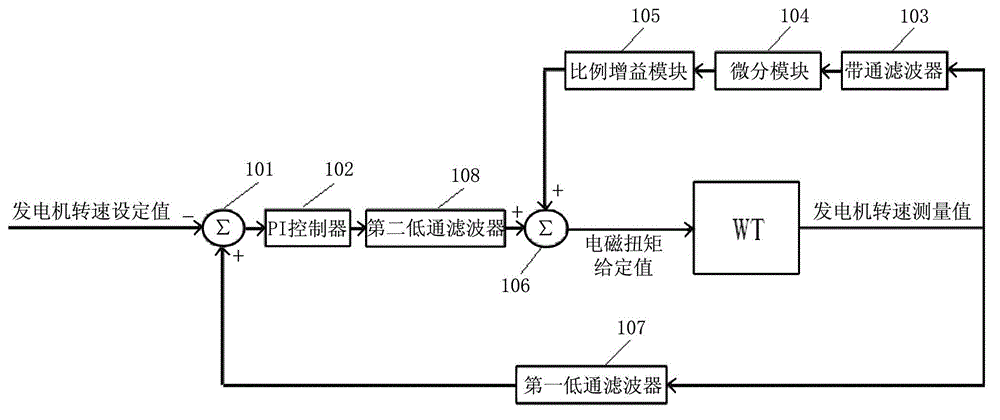
[0028] figure 1 It is a block diagram showing an IN-PLANE third-order frequency vibration suppression system for fan blades according to an embodiment of the present invention.

[0029] refer to figure 1 , the fan blade IN-PLANE third-order frequency vibration suppression system includes a generator speed measurement module (not shown), a comparator 101, a proportional-integral (PI) controller 102, a band-pass filter 103, a differential module 104, and a proportional gain module 105 and adder 106.

[0030] The generator speed measurement module is installed in the wind turbine nacelle, and measures the generator speed (ie, obtains the measured value of the generator speed)....


PUM


Abstract

The invention provides a system and method for abating three-step frequency vibration of fan blades on an IN-PLANE. The system comprises a generator rotation speed measuring module, a comparator, a proportion integral controller, a band-pass filter, a differential module, a proportional gain module and a summing unit. The generator rotation speed measuring module is used for obtaining a measured value of the generator rotation speed, and the comparator is used for comparing the measured value of the generator rotation speed and a set value of the generator rotation speed. The proportion integral controller carries out the proportional integral operation on a comparison result and obtains a first control input value of generator electromagnetic torque, and the band-pass filter is used for extracting three-step inherent frequency signals of the fan blades on the IN-PLANE from the measured value of the generator rotation speed. The differential module is used for carrying out the differential operation on the band-pass filtration result, and the proportional gain module is used for carrying out proportional gain amplification on the differential operation result and obtaining a second control input value of the generator electromagnetic torque. The summing unit is used for carrying out superposition of the first input value and the second input value of the generator electromagnetic torque to obtain the set value of the generator electromagnetic torque. The set value of the generator electromagnetic torque is used for controlling electromagnetic torque of a fan, so that the three-step frequency vibration amplitude of the fan blades on the IN-PLANE is reduced.

Description

technical field [0001] The invention belongs to the field of wind power generation, and relates to a system and method for suppressing IN-PLANE third-order frequency vibration of fan blades. Background technique [0002] As the design capacity and blade length of the wind turbine (Wind Turbine, MT, referred to as wind turbine) increase, the third-order natural frequency signal of the blade IN-PLANE shows a trend of lower frequency and a sharp increase in signal strength (here, IN -PLANE refers to the plane on which the fan impeller rotates, i.e. the plane of rotation of the fan impeller), resulting in the generator speed measurement and the side-side direction of the fan tower (also called the tower) (the direction perpendicular to the windward direction of the impeller , which is the direction perpendicular to the wind direction) in the acceleration signal, the third-order natural frequency signal of the blade IN-PLANE is obvious. The obvious third-order natural frequency ...

Claims


Application Information

Patent Timeline
IPC IPC(8): F03D7/00F03D11/00
CPCY02E10/72
Inventor 王明江
Owner BEIJING GOLDWIND SCI & CREATION WINDPOWER EQUIP
Learn More