
Hydraulic jack with automatic speed regulation function

A hydraulic jack and automatic speed regulation technology, which is applied in fluid pressure actuation devices, fluid pressure actuation system components, lifting devices, etc., can solve problems such as insufficient safety, high machining accuracy, and potential safety hazards, and achieve stable and reliable performance , Guarantee work efficiency and ensure the effect of safety

Inactive Publication Date: 2013-10-02
CHANGSHU TONGRUN AUTO ACCESSORY
View PDF7 Cites 4 Cited by
  • Summary
  • Abstract
  • Description
  • Claims
  • Application Information

AI Technical Summary

Problems solved by technology

The disadvantage of this oil return valve structure is: when the oil return valve is under a large load, due to the high pressure in the cylinder cavity, the flow rate of the hydraulic oil is fast, and the falling speed of the load is also fast, so the safety is relatively poor. It is easy to injure the operator or damage the equipment
The defect of this oil return valve structure is that when the oil return valve is opened under a large load, the load will suddenly drop rapidly and then "brake" suddenly - entering a slow drop, which has a huge safety hazard. The safety is not as good as the conventional hydraulic jacks currently on the market; secondly, because the oil return valve of the jack produced according to the above-mentioned technical scheme cannot be completely and quickly opened, it will cause the load to drop suddenly and then "brake" suddenly ——Entering a slow decline, it does not meet the relevant regulations of domestic and international standards, and it is a substandard product; third, the seals in the oil return valve and the one-way valve are cone valve seals, which require high processing accuracy and are not The pass rate is high. Once there is a problem with the seal, the oil return valve will be opened when the load is loaded, and the load will suddenly drop rapidly, so there is also a huge safety hazard, and the production cost is relatively high.
[0004] In addition, in the existing hydraulic jack, when the external force pulls the piston rod assembly out, a negative pressure will be formed in the cylinder chamber at the bottom of the piston, and when the external force is removed, the piston rod assembly will retract into the cylinder

Method used


Image

  • Hydraulic jack with automatic speed regulation function
  • Hydraulic jack with automatic speed regulation function
  • Hydraulic jack with automatic speed regulation function

Examples


Embodiment Construction

[0021] In order to enable the public to fully understand the technical essence and beneficial effects of the present invention, the applicant will describe in detail the specific implementation of the present invention below in conjunction with the accompanying drawings, but the applicant's description of the embodiments is not a limitation to the technical solution. Changes in the form of the inventive concept rather than in substance should be regarded as the protection scope of the present invention.

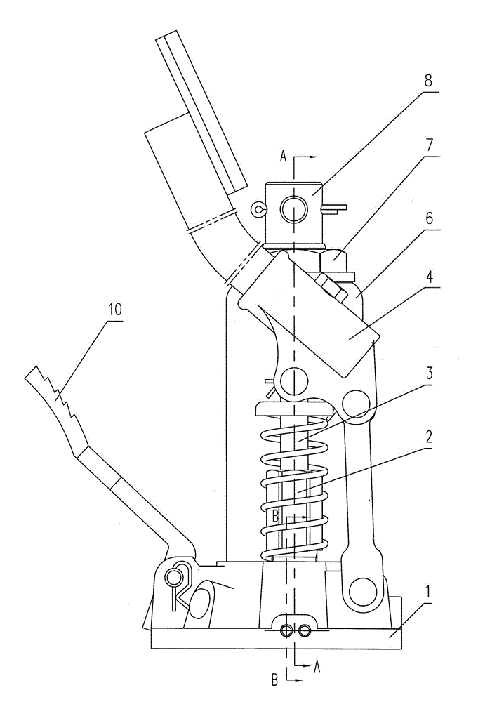
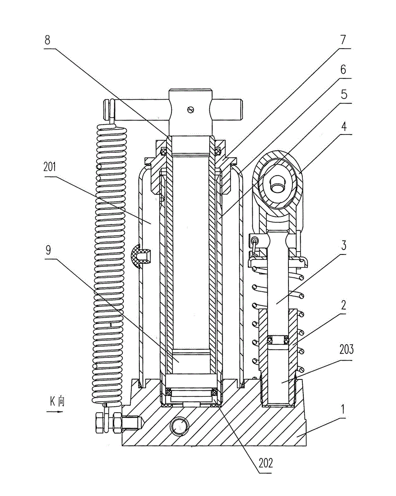
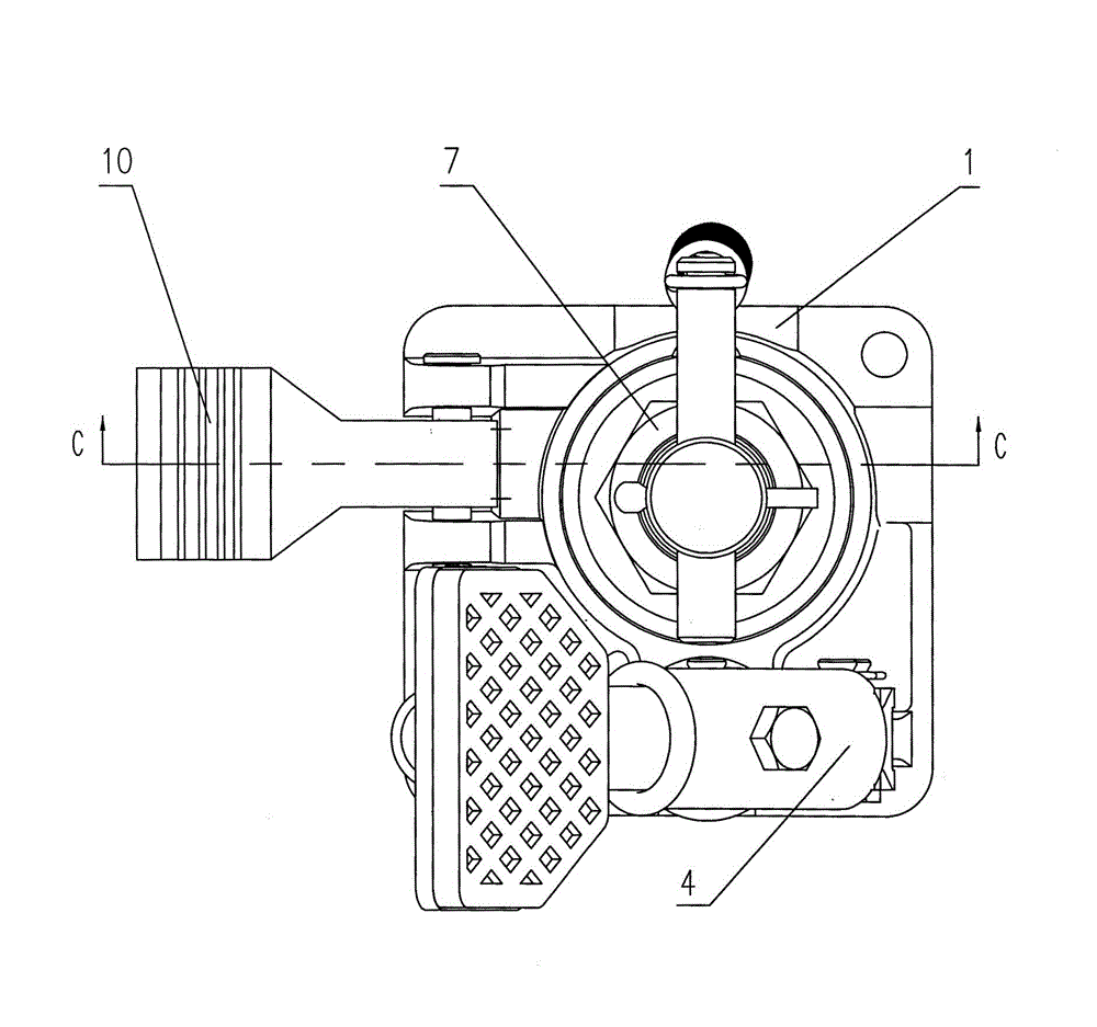
[0022] see figure 1 , figure 2 , image 3 , Figure 4 , Figure 5 , Figure 6 and Figure 7, the present invention relates to a hydraulic jack with an automatic speed regulating function, comprising a base 1, a pump body 2 fixed on the base 1, a pump core 3 arranged in the pump body 2, a pump connected to the base 1 and the pump core 3 The oil pump pedal assembly 4, the oil cylinder 5 and the outer cover 6 fixed on the base 1, the top cap 7 arranged on the oil cylinder...


PUM


Abstract

The invention discloses a hydraulic jack with an automatic speed regulation function and belongs to the technical field of hoisting equipment. The hydraulic jack comprises base, a pump body, a pump core, an oil pump pedal assembly, an oil cylinder, a jacket, a top cap, a piston rod assembly and a piston. An oil storage cavity is formed between the oil cylinder and the jacket, and an oil cylinder cavity is formed between the lower end of the piston and the base in the oil cylinder. The hydraulic jack is characterized in that the base is also provided with a slow oil return line, a rapid oil return valve structure and a hydraulic control one-way valve structure. The hydraulic jack can go down at a normal speed when in no load or light load, and slowly goes down when bearing a higher load, and therefore, the safety of use can be ensured, and the work efficiency is ensured. When the piston rod assembly is pulled out, hydraulic oil in the oil storage cavity enters the oil cylinder cavity by oil suction lines and oil suction one-way valve steel balls, and negative pressure cannot be formed after the hydraulic oil is supplemented into the oil cylinder cavity. After an external force is removed, the oil suction one-way valve steel balls are closed, and the piston rod assembly cannot be retracted into the oil cylinder. The hydraulic jack with the automatic speed regulation function is simple in structure and stable and reliable in performance, and is suitable for low-cost mass production.

Description

technical field [0001] The invention belongs to the technical field of lifting equipment, and in particular relates to a hydraulic jack with an automatic speed regulation function, which is an improvement on the oil return valve structure and the oil circuit in the existing hydraulic jack. Background technique [0002] The oil return valve structure of the existing hydraulic jack generally includes an oil return valve stem and a steel ball. The oil return valve stem and the base are connected by threads. By turning the oil return valve stem to loosen or tighten the steel ball, the oil return valve is opened or closed. valve. The disadvantage of this oil return valve structure is: when the oil return valve is under a large load, due to the high pressure in the cylinder cavity, the flow rate of the hydraulic oil is fast, and the falling speed of the load is also fast, so the safety is relatively poor. It is easy to injure the operator or damage the equipment. [0003] China...

Claims


Application Information

Patent Timeline
Patent Type & Authority Applications(China)
IPC IPC(8): B66F3/25F15B21/00F15B13/02
Inventor 常良成
Owner CHANGSHU TONGRUN AUTO ACCESSORY
Learn More