
Electric energy meter test equipment

A technology of testing equipment and electric energy meters, which is applied in the direction of measuring devices, measuring electrical variables, instruments, etc., can solve the problems of high test pressure and low test efficiency, and achieve the effect of improving pass rate, improving utilization efficiency, and balancing the detection system

Active Publication Date: 2013-09-25
STATE GRID CORP OF CHINA +2
View PDF11 Cites 9 Cited by
  • Summary
  • Abstract
  • Description
  • Claims
  • Application Information

AI Technical Summary

Problems solved by technology

[0003] The purpose of the present invention is to provide a kind of electric energy meter test equipment, in order to solve the problem that the test pressure is too large and the test efficiency is low due to too many test items of the standard meter adjustment station

Method used


Image

  • Electric energy meter test equipment
  • Electric energy meter test equipment
  • Electric energy meter test equipment

Examples


Embodiment Construction

[0023] The present invention will be described in further detail below in conjunction with the accompanying drawings.

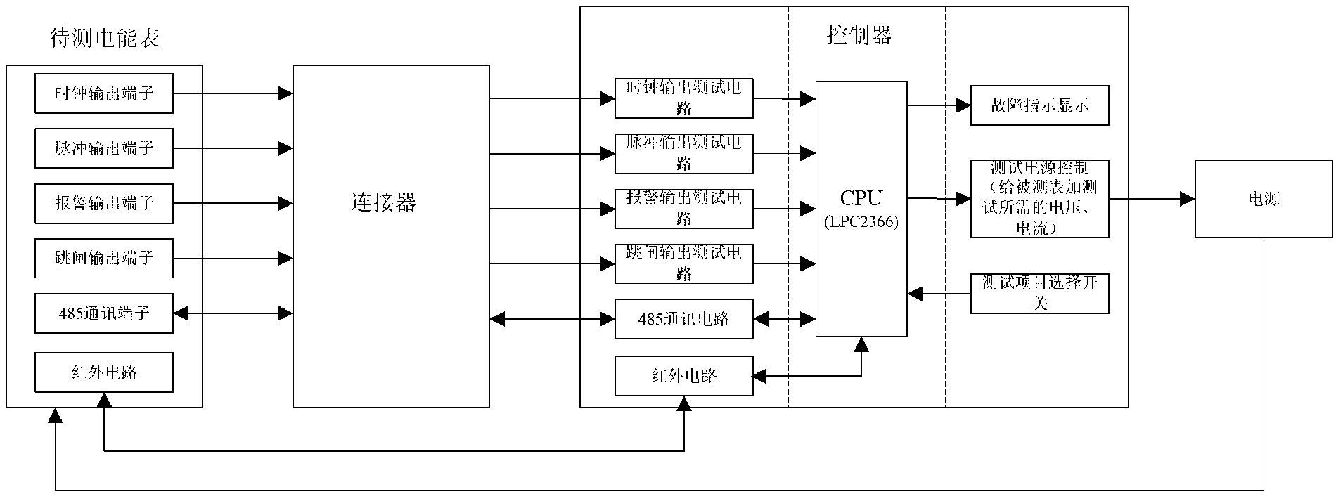
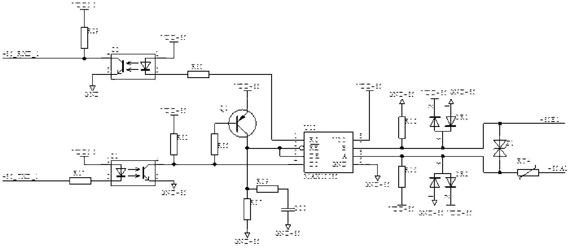
[0024] The electric energy meter test equipment has a control board, the control board integrates the controller and connects with it such as figure 2 , 3 , The test circuit shown in 4 and 5, the 485 communication interface circuit, and the infrared communication interface circuit.

[0025] The controller on the control board starts the corresponding test items in the corresponding circuit by reading the position of the test item selection button (dip switch).

[0026] Such as figure 1 As shown, in this embodiment, the controller of the electric energy meter test equipment is connected to multiple test circuits, and each test circuit (clock output test circuit, pulse output test circuit, trip output test circuit, alarm output test circuit) is connected to the electric energy to be tested Meter clock output, pulse output, trip output, alarm output terminal...


PUM


Abstract

The invention relates to electric energy meter test equipment. A control circuit of the electric energy meter test equipment comprises a controller, a 485 communication interface circuit, and at least one test circuit used for carrying out testing on clock output, pulse output, alarm output and tripping output. The test circuit is provided with an input interface connected with corresponding output of an electric energy meter to be tested in corresponding testing, and the corresponding output comprises the clock output, the pulse output, the alarm output and the tripping output. An output interface of the test circuit is connected with the controller, the two ends of the 485 communication interface circuit are connected with the controller and the electric energy meter respectively, and the controller is further in input connection with a switch used for switching test items. Before the electric energy meter passes through an alignment table of a standard meter, the tripping output, alarming and other items are tested through the test equipment, utilization efficiency of the alignment table of the standard table is improved, and production capacity is promoted.

Description

technical field [0001] The invention relates to an electric energy meter testing device. Background technique [0002] At present, in the traditional manufacturing mode, electric energy meters need to go through several major processes of assembly, electrical testing, inspection, and packaging. In this mode, the electrical testing items are the most, including tripping output testing, alarm testing, pulse output testing, clock output testing, 485-channel test, sub-element low-voltage capability test, button test, infrared communication test, precision adjustment, latent start test, etc. Therefore, electrical testing has the most significant impact on production capacity: first, electrical testing needs to be adjusted using standard tables certified by national institutions Second, there are many test items, the degree of automation is low, workers are prone to make mistakes and the efficiency is low; thirdly, when the electric energy meter with unqualified incoming materials...

Claims


Application Information

Patent Timeline
Patent Type & Authority Applications(China)
IPC IPC(8): G01R35/04
Inventor 刘静然陈新春张敬伟单鲜堂陈银凯何小辉李淑红王升升方明义李永强
Owner STATE GRID CORP OF CHINA
Learn More