
Steel truss-prestressed concrete bridge deck combined bridge girder and construction method thereof

A bridge deck, steel truss technology, applied in the direction of erecting/assembling bridges, bridges, bridge materials, etc., can solve the problems of reducing the overall mechanical performance, difficult crack control, difficult maintenance, etc., to improve the torsional stiffness and shear resistance. Ability, improve construction quality and construction efficiency, the effect of unlimited beam storage time

Inactive Publication Date: 2013-09-18
CHONGQING JIAOTONG UNIVERSITY +1
View PDF8 Cites 13 Cited by
  • Summary
  • Abstract
  • Description
  • Claims
  • Application Information

AI Technical Summary

Problems solved by technology

[0003] (1) Prestressed concrete simply supported T-beam bridges are prefabricated on site, and affected by site construction conditions and ambient temperature, the construction quality is highly discrete and construction management is difficult
[0004] (2) The tensile strength of the concrete structure is low in the early stage. When the prestressed pipeline deviates greatly, it often produces longitudinal cracks along the bridge span direction at the web, bottom plate or horseshoe during tension, making crack control difficult
When the prefabrication and installation deviation of each T-beam is large, the lateral butt joint deviation of the transverse diaphragm is large, and the vertical height difference of the bridge deck is large, which reduces the overall mechanical performance
In addition, the construction of the connection of the T-beam transverse diaphragm and the connection of the bridge deck is mostly high-altitude operations, and it is difficult to control the construction accuracy
[0006] (4) The hoisting weight of the prefabricated T-beam is large
The hoisting weight of each girder with a span of 30 meters to 50 meters is about 80 tons to 150 tons. The risk of hoisting is high and the cost of hoisting is high.
[0007] (5) The torsional capacity of the prefabricated T-beam is insufficient, and the risk of torsional cracking during construction is high
[0008] (6) The prestressed concrete simply supported T-beam bridge has a large self-weight, which limits the spanning capacity, and the span generally does not exceed 50 meters
In some areas, the pier height reaches more than 100 meters, and the layout of bridge spans is unreasonable and unsightly
[0009] (7) The beam storage time of prestressed concrete structure prefabricated parts is limited, generally no more than 6 months, which requires a large prefabricated site and manpower and material resources
[0013] (1) The corrosion problem of steel structural components is prominent, and the cost of anti-corrosion treatment and maintenance is relatively high
[0014] (2) The shear bond between the steel truss and the concrete bridge deck is easy to corrode and difficult to maintain
[0015] (3) The waterproofing of the concrete bridge deck is difficult to control, which will aggravate the corrosion or breakage of the shear keys, endangering the safety of the bridge
[0016] (4) Insufficient torsion and shear resistance of steel trusses

Method used


Image

  • Steel truss-prestressed concrete bridge deck combined bridge girder and construction method thereof
  • Steel truss-prestressed concrete bridge deck combined bridge girder and construction method thereof
  • Steel truss-prestressed concrete bridge deck combined bridge girder and construction method thereof

Examples


Embodiment Construction

[0081] The first object of the present invention is to provide a steel truss prestressed concrete composite bridge, the steel structural members of which are not easily corroded and the maintenance cost is low. The second object of the present invention is to provide a construction method for a steel truss prestressed concrete composite bridge.

[0082] The following will clearly and completely describe the technical solutions in the embodiments of the present invention with reference to the accompanying drawings in the embodiments of the present invention. Obviously, the described embodiments are only some, not all, embodiments of the present invention. Based on the embodiments of the present invention, all other embodiments obtained by persons of ordinary skill in the art without making creative efforts belong to the protection scope of the present invention.

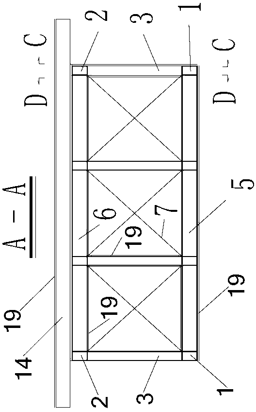
[0083] see Figure 1-Figure 4 , the steel truss prestressed concrete deck composite bridge provided by the present...


PUM


Abstract

The invention discloses a steel truss-prestressed concrete bridge deck combined bridge girder which comprises a steel truss and a bridge deck laid on the steel truss, wherein the steel truss comprises a plurality of vertical truss pieces and two horizontal bracing systems, namely the upper horizontal bracing system and the lower horizontal bracing system; the vertical truss pieces are arranged side by side in the direction of a bridge span; the two horizontal bracing systems parallel to each other are respectively arranged at the tops and the bottoms of the vertical truss pieces; FRP (Fiber Reinforced Polymer) structures are stuck to the surfaces of the components of the vertical truss pieces; FRP structures are laid onto the left surfaces and the right surfaces of the vertical truss pieces to enable the vertical truss pieces to form webs; an FRP structure is stuck to the surface of the component of the upper horizontal bracing system; FRP structures are stuck to the upper surface and the lower surface of the upper horizontal bracing system to enable the upper horizontal bracing system to form a top plate; an FRP structure is stuck to the surface of the component of the lower horizontal bracing system; FRP structures are stuck to the upper surface and the lower surface of the lower horizontal bracing system to enable the lower horizontal bracing system to form a bottom plate; each FRP structure comprises FRP woven roving and FPR chopped strand mats are stuck to two surfaces of the FRP structure. The invention further discloses a construction method of the steel truss-prestressed concrete bridge deck combined bridge girder.

Description

technical field [0001] The invention relates to the technical field of civil engineering, more specifically, to a steel truss prestressed concrete deck composite bridge and a construction method thereof. Background technique [0002] Prestressed concrete simply supported T-beam bridge is a bridge type widely used at present, with a span of 30 meters to 50 meters being the most common. When there are multiple spans, the existing technology often adopts simply supported-structure continuous or simply supported-deck continuous. The main defects of this structure are as follows: [0003] (1) Prestressed concrete simply supported T-beam bridges are prefabricated on site, and affected by site construction conditions and ambient temperature, the construction quality is highly discrete and construction management is difficult. [0004] (2) The tensile strength of the concrete structure is low in the early stage. When the prestressed pipe deviates greatly, it often produces longitud...

Claims


Application Information

Patent Timeline
Patent Type & Authority Applications(China)
IPC IPC(8): E01D12/00E01D21/00E01D101/28
Inventor 吴国松胡嘉鸿
Owner CHONGQING JIAOTONG UNIVERSITY
Learn More