A pulverized coal dynamic separator using curved blades

A separator and blade technology, applied in the direction of solid separation, separating solids from solids with airflow, chemical instruments and methods, etc., can solve the problems of large blade wear, weak airflow, and difficult to filter large coal powder particles, etc. Achieve the effect of improving coal fineness, reasonable design and simple structure

Active Publication Date: 2015-09-23
HUADIAN ELECTRIC POWER SCI INST CO LTD
View PDF9 Cites 0 Cited by
  • Summary
  • Abstract
  • Description
  • Claims
  • Application Information

AI Technical Summary

Problems solved by technology

[0003] There are also some coal powder dynamic separators of other structures at present. As the publication date is September 06, 2000, and the publication number is CN2394729, a Chinese patent discloses a dynamic coarse powder separator. One of the main equipment of the storage type pulverizing system in the factory can separate the qualified coal powder from the air flow, but it is difficult to effectively improve the fineness of the coal powder and effectively reduce the wear on the blades
Another example is that on April 25th, 2012, the publication date is CN202199508U, a Chinese patent that discloses a rotary coarse powder separator combined with static and movable blades. Including the separator shell, the shell is provided with a powder outlet pipe, a powder inlet pipe and a powder return pipe that communicate with the inside of the shell; the shell is provided with an inner cylinder, the upper end of the inner cylinder is open, and the lower end is communicated with the powder return pipe ; Between the upper end of the inner cylinder and the shell of the separator, there are a plurality of stationary blades arranged in a circle; a driving motor is installed on the shell, and the motor shaft passes through the upper shell of the separator vertically and enters the separator. inside the formed circle; the moving impeller rotor is connected to the motor shaft, and a plurality of moving blades are installed on the moving impeller rotor according to the circumference; driven by the motor shaft, the moving impeller rotor drives the moving blades to rotate to form a dynamic rotation separation area, and the static and moving blades are combined The structure of the type rotary coarse powder separator is complicated, it is difficult to effectively improve the fineness of coal powder, and it is difficult to effectively reduce the wear on the blades
[0004] The blades in the existing pulverized coal dynamic separator are usually of straight blade structure, the airflow generated is relatively weak, and the flow channel formed cannot make the airflow flowing through it form a certain rotation, and it is difficult to further filter large pulverized coal particles. Particles are more abrasive to blades

Method used


Image

  • A pulverized coal dynamic separator using curved blades
  • A pulverized coal dynamic separator using curved blades
  • A pulverized coal dynamic separator using curved blades

Examples


Embodiment 1

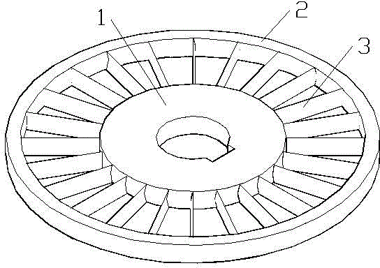
[0024] see figure 1 , Figure 4 to Figure 6 In this embodiment, the pulverized coal dynamic separator using curved blades includes a rotating shaft disc 1, a ring 2 and several blades 3, and the pulverized coal dynamic separator is a rotating planar structure.

[0025] The blade 3 in this embodiment is a curved surface structure, and the blade 3 is provided with a concave surface 31 and a convex surface 32. The concave surface 31 in the blade 3 is arc-shaped, and the convex surface 32 in the blade 3 is semi-elliptical. The two endpoints of the semi-ellipse coincide with the two endpoints of the semi-ellipse respectively, the line between the two endpoints of the semi-ellipse is the major axis of the ellipse, the length of the major axis of the ellipse is the chord length of the arc, and the ellipse The length of the minor axis is 6 / 10 of the radius of the arc.

[0026] The radius of the rotating shaft disc 1 in this embodiment is smaller than the radius of the ring 2, the ro...

Embodiment 2

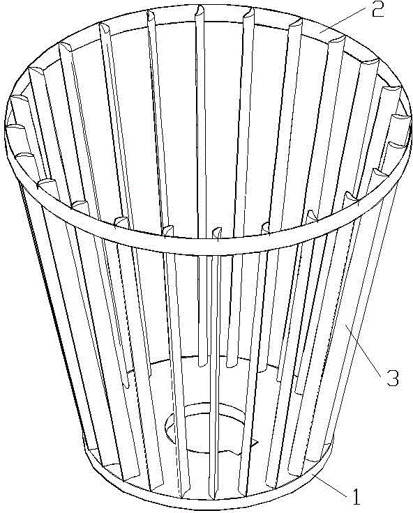
[0033] see figure 2 , Figure 4 to Figure 6 , The pulverized coal dynamic separator using curved blades in this embodiment includes a rotating shaft disk 1, a ring 2 and several blades 3, and the pulverized coal dynamic separator has a conical structure.

[0034] The blade 3 in this embodiment is a curved surface structure, and the blade 3 is provided with a concave surface 31 and a convex surface 32. The concave surface 31 in the blade 3 is arc-shaped, and the convex surface 32 in the blade 3 is semi-elliptical. The two endpoints of the semi-ellipse coincide with the two endpoints of the semi-ellipse respectively, the line between the two endpoints of the semi-ellipse is the major axis of the ellipse, the length of the major axis of the ellipse is the chord length of the arc, and the ellipse The length of the minor axis is 6 / 10 of the radius of the arc.

[0035] The radius of the rotating shaft disc 1 in this embodiment is smaller than the radius of the ring 2, the rotatin...

Embodiment 3

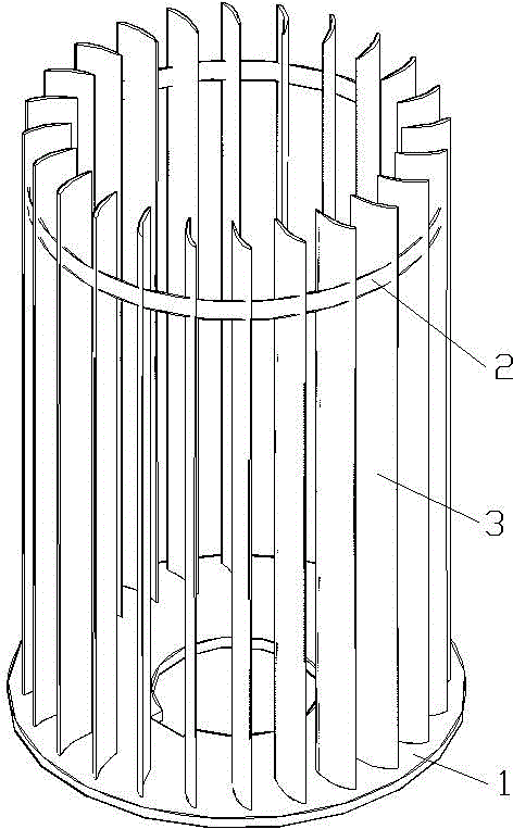
[0038] see Figure 3 to Figure 6 , The pulverized coal dynamic separator using curved blades in this embodiment includes a rotating shaft disc 1, a ring 2 and several blades 3, and the pulverized coal dynamic separator has a cylindrical structure.

[0039] The blade 3 in this embodiment is a curved surface structure, and the blade 3 is provided with a concave surface 31 and a convex surface 32. The concave surface 31 in the blade 3 is arc-shaped, and the convex surface 32 in the blade 3 is semi-elliptical. The two endpoints of the semi-ellipse coincide with the two endpoints of the semi-ellipse respectively, the line between the two endpoints of the semi-ellipse is the major axis of the ellipse, the length of the major axis of the ellipse is the chord length of the arc, and the ellipse The length of the minor axis is 6 / 10 of the radius of the arc.

[0040] The radius of the rotating shaft disc 1 in this embodiment is greater than or equal to the radius of the ring 2, the rota...


PUM


Abstract

The invention relates to a dynamic pulverized coal separator adopting curved blades. A blade of a conventional dynamic pulverized coal separator commonly adopts a straight blade structure, generated airflow is poorer, and abrasion of pulverized coal grains to the blade is larger. The dynamic pulverized coal separator adopting the curved blades comprises a rotating shaft disc, a circular ring as well as a plurality of blades fixed on the rotating shaft disc and the circular ring, and is characterized in that each blade adopts a curved structure and provided with a concave surface and a convex surface, wherein the concave surface of the blade is circular-arc-shaped; the convex surface of the blade is semi-elliptical; two end points of the circular arc coincide with those of the semi-ellipse; a connecting line of the two end points of the semi-ellipse is a long axis of an ellipse; the length of the long axis of the ellipse is the chord length of the circular arc; the length of a short axis is six tenths of the radius of the circular arc; and the concave surfaces of the plurality of blades are arranged in a clockwise or counter-clockwise direction. The dynamic pulverized coal separator adopting the curved blades is reasonable in structural design, the generated rotational airflow is stronger, and the abrasion of the pulverized coal grains on the blades is reduced.

Description

technical field [0001] The invention relates to a pulverized coal dynamic separator, in particular to a pulverized coal dynamic separator using curved blades, which can be applied to dynamic separators in industrial sectors where gas-solid two-phase separation is required. Background technique [0002] In all production processes accompanied by gas-solid two-phase, gas-solid separation is an indispensable link. has a wide range of applications. The working principles of commonly used gas-solid separation devices are: gravity separation mechanism, inertial separation mechanism, centrifugal separation mechanism and charge separation mechanism. The static and dynamic separators used for the separation of coarse and fine powder in coal mills in the power industry use the inertial separation mechanism to separate the coarse and fine powder. The coarse powder enters the coal mill for re-grinding, while the fine powder enters the furnace with the upward force of the primary wind. ...

Claims


Application Information

Patent Timeline
IPC IPC(8): B07B7/083B07B11/02
Inventor 孙科秦大川靳士奇陈剑
Owner HUADIAN ELECTRIC POWER SCI INST CO LTD
Why Eureka
Try Eureka