
Low-temperature atomizing air cooler and its realization method

An implementation method and technology of a cooling fan, applied in metal processing machinery parts, maintenance and safety accessories, metal processing equipment, etc., can solve the problems of high cost input, large temperature loss, rapid tool wear, etc., to achieve energy-saving and clean processing, High-efficiency cutting process and the effect of improving cutting stress

Active Publication Date: 2016-03-30
成都凯里恩科技有限公司
View PDF8 Cites 0 Cited by
  • Summary
  • Abstract
  • Description
  • Claims
  • Application Information

AI Technical Summary

Problems solved by technology

[0002] In the cutting process of machine tools, the traditional method of cooling workpieces and tools is to use coolant to spray cooling and lubricating the workpieces and tools. This cooling method has low production efficiency and high cost investment, and will lead to A large amount of waste liquid is produced, the waste liquid is difficult to recycle, the treatment cost is high, and the environment is also greatly polluted
[0003] Further, methods of micro-oil or liquid atomization of normal-temperature air and low-temperature air flow cooling processing have been successively produced; among them, the micro-oil atomization technology of normal-temperature air is to mix the normal-temperature air with the oil circuit through the regulating valve, and pass through the air pipe through the nozzle. One-time atomization is sprayed to the cutting area, so as to replace the cutting fluid to carry out atomization and cooling of the workpiece at room temperature. This method mainly has the following defects: (1) The temperature of the air flow is high, generally 15-25 ° C; (2) The cooling efficiency is low , only suitable for cutting with a small amount of metal removal; (3) The atomized particles of trace oil are coarse, and the atomization effect is poor, which directly affects the lubrication effect
It mainly has the following defects: (1) there is only cold air without trace oil or liquid lubrication, only dry cutting can be realized, the friction force is large, the wear of the tool is fast, and the cooling efficiency is low; (2) the water and oil in the air Drying adopts the method of variable pressure suction, and the use time of the adsorbent is short; (3) The metal foam insulation tube is used for heat preservation, and the long-distance transportation will cause a large temperature loss
[0005] Although the above two cooling technologies can replace cutting fluid processing, the application range is too small and the effect is not good

Method used


Image

  • Low-temperature atomizing air cooler and its realization method
  • Low-temperature atomizing air cooler and its realization method
  • Low-temperature atomizing air cooler and its realization method

Examples


Embodiment 1

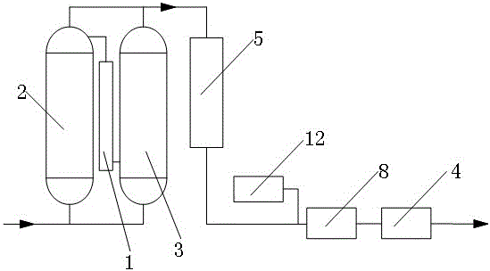
[0040] In the cutting process of existing machine tools, the cooling of workpieces and tools is mainly divided into three types: traditional coolant spray cooling and lubrication; micro oil atomization of normal temperature air with lubrication but poor cooling effect; low temperature air without lubrication flow cooling. In order to overcome the above defects, this embodiment provides a low-temperature atomizing air cooler, such as figure 1 As shown, the low-temperature atomizing air cooler has changed the traditional cutting method of cooling with oil and coolant, and at the same time organically combined the micro-oil atomization of normal temperature air and the cooling technology of low-temperature air flow into one, and the machine under a certain pressure After the normal temperature air is dried and purified, the airflow is cooled by the refrigeration system to form a low-temperature airflow, and then the liquid or oil is atomized twice to atomize a small amount of oil...

Embodiment 2

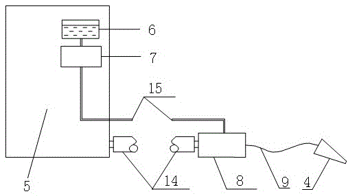
[0056] The difference between this embodiment and Embodiment 1 is that the structure of the nozzle is different, such as Figure 4 As shown, the nozzle in this embodiment is composed of a nozzle body 10, a nozzle opening 11 and a valve core 13 arranged between the two. The adjustable pipe is connected to the nozzle body, the mixing block and the nozzle are connected to the nozzle through the adjustable pipe 9, the liquid is sprayed from the aperture (1mm in diameter) in the center of the valve core, and the low-temperature air flow is from the center hole of the valve core and the gap between the nozzle body and the nozzle mouth. The gap is sprayed to realize the second atomization, and the arrow in the figure indicates the direction of the mist.


PUM


Abstract

The invention discloses a low-temperature atomizing air cooler and an achieving method thereof. The low-temperature atomizing air cooler solves the problems that a normal-temperature air microscale oil atomizing technique in the prior art is high in temperature and poor in cooling effect, and low-temperature air flow cooling processing in the prior art is low-temperature air flow dry type cutting processing so as to be insufficient in lubrication and quick in cutter abrasion. The low-temperature atomizing air cooler comprises a drying tower, a refrigerating system, a microscale oil supplying mechanism, a mixing block, a spray nozzle and a PLC control system, wherein the drying tower is used for drying and cleaning air from the outside of the low-temperature atomizing air cooler, the refrigerating system is communicated with the drying tower through a pipeline and used for cooling air dried by the drying tower to form low-temperature air flow, the microscale oil supplying mechanism can inject oil or fluid into the mixing block through an oil pipe, the mixing block is respectively communicated with the microscale oil supplying mechanism and the refrigerating system and used for primarily atomizing the oil or fluid injected into the mixing block and low-temperature air flow to form low-temperature air flow fluid fog, the spray nozzle is communicated with the mixing block and can secondarily atomize the low-temperature air flow fluid fog obtained from primary atomization to obtain low-temperature atomized air flow.

Description

technical field [0001] The invention belongs to the technical field of cooling and lubricating in metal cutting, and in particular relates to a low-temperature atomizing air cooler and a realization method thereof. Background technique [0002] In the cutting process of machine tools, the traditional method of cooling workpieces and tools is to use coolant to spray cooling and lubricating the workpieces and tools. This cooling method has low production efficiency and high cost investment, and will lead to A large amount of waste liquid is generated, which is difficult to recycle, has high processing costs, and causes great pollution to the environment. [0003] Further, methods of micro-oil or liquid atomization of normal-temperature air and low-temperature air flow cooling processing have been successively produced; among them, the micro-oil atomization technology of normal-temperature air is to mix the normal-temperature air with the oil circuit through the regulating valv...

Claims


Application Information

Patent Timeline
Patent Type & Authority Patents(China)
IPC IPC(8): B23Q11/10
Inventor 杨伦
Owner 成都凯里恩科技有限公司
Learn More