Backlight module and membrane positioning structure thereof

A positioning structure and backlight module technology, applied in the direction of light source fixing, optical, electric light source, etc., can solve the problems of diaphragm jumping, warping, diaphragm wrinkles, etc., to prevent jumping, improve production capacity and product yield , to ensure the effect of optical quality

Inactive Publication Date: 2013-09-04
TCL CHINA STAR OPTOELECTRONICS TECH CO LTD
View PDF4 Cites 2 Cited by
  • Summary
  • Abstract
  • Description
  • Claims
  • Application Information

AI Technical Summary

Problems solved by technology

However, the design of the backlight module tends to be thinner, so that the height of the rivet column cannot be too high, and the upper end of the rivet column is usually exposed by about 0.5~0.8 mm. In the actual assembly process, the backlight module is prone to diaphragm jumping during the moving process , Displacement problems, leading to problems such as diaphragm folds and warpage

Method used


Image

  • Backlight module and membrane positioning structure thereof
  • Backlight module and membrane positioning structure thereof
  • Backlight module and membrane positioning structure thereof

Examples


Embodiment Construction

[0020] It should be understood that the specific embodiments described herein are only used to explain the present invention, and not to limit the present invention.

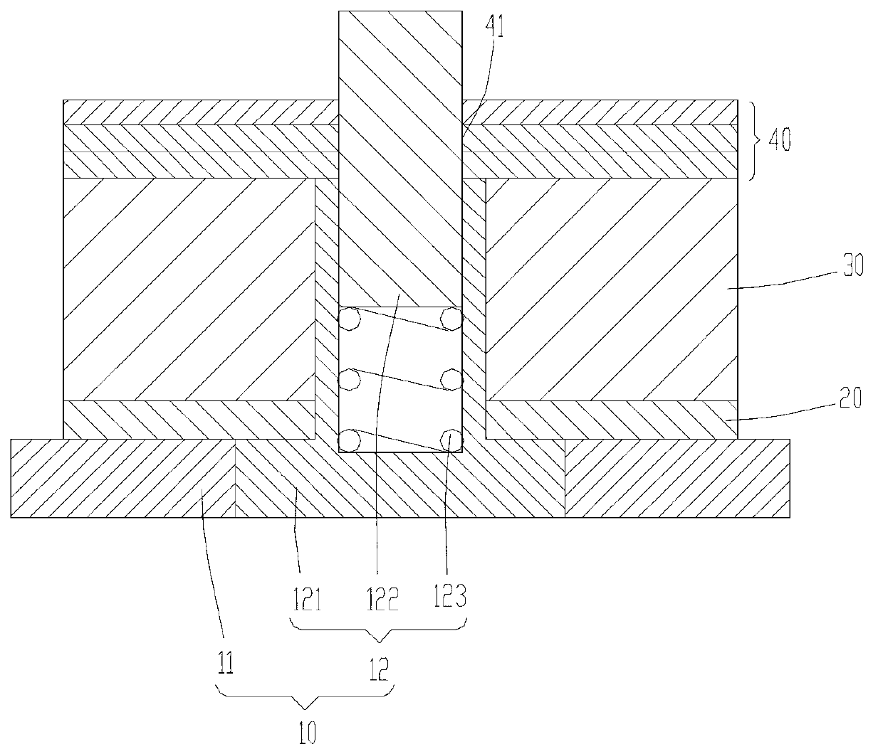
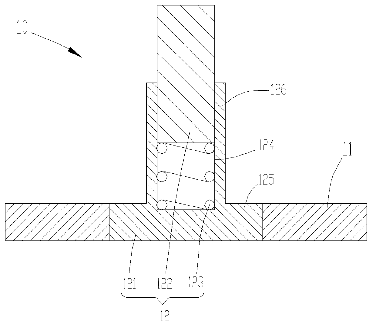
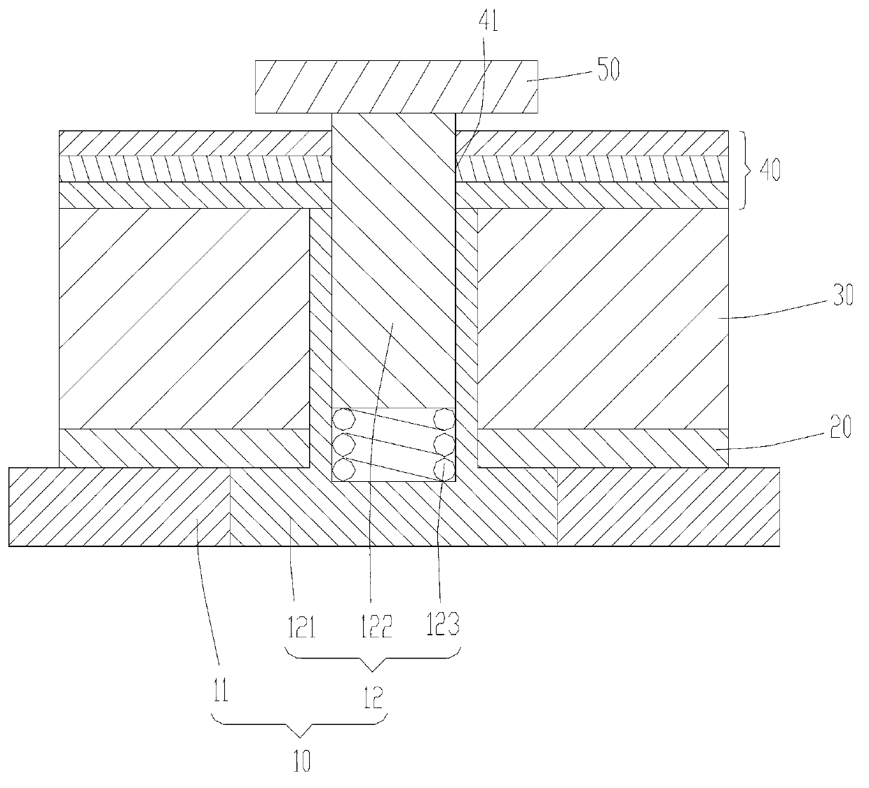
[0021] Such as Figure 1 to Figure 3 What is shown is a preferred embodiment of the backlight module of the present invention.

[0022] The backlight module includes a diaphragm positioning structure 10, a reflective sheet 20, a light guide plate 30 and a diaphragm 40.

[0023] The diaphragm positioning structure 10 includes a back plate 11 and a positioning member 12. The positioning member 12 includes a base 121, a positioning column 122 and an elastic body 123. The base 121 is fixedly connected with the back plate 11, the base 121 is provided with a guide hole 124, the elastic body 123 and the positioning post 122 are sequentially arranged in the guide hole 124, and the elastic body 123 is sandwiched between the bottom surface of the guide hole 124 and the positioning post 122 . The elastic body 123 is an element...


PUM


Abstract

The invention provides a membrane positioning structure which comprises a backplane and a positioning piece, wherein the positioning piece comprises a base and a positioning column, the base is fixedly connected with the backplane, and the positioning column is arranged on the base in a telescopic mode and protrudes out of one side, facing towards a membrane, of the backplane. According to the membrane positioning structure, the membrane is positioned through the telescopic positioning column arranged on the base; when the membrane is assembled, the positioning column stretches outwards to provide a larger length for positioning of the membrane, and tripping and displacement of the membrane can be prevented; labor-hour waste and quality abnormal damage brought by the tripping and the displacement of the membrane are effectively reduced, productivity and the yield of products are improved, and the optical quality of a backlight module is guaranteed. The invention further provides the backlight module with the membrane positioning structure.

Description

Technical field [0001] The present invention relates to the technical field of liquid crystal display, in particular to a backlight module and a film positioning structure thereof. Background technique [0002] The backlight module is mainly composed of light-emitting source, reflector, optical film, light guide plate, back plate and other related devices. The main function of an optical film with a prism structure is to condense light. Some types of optical brightness enhancement films and polarizers can reflect, recycle, and reuse the polarized light that cannot pass through the polarizer to improve the effective utilization of light. This requires accurate positioning and installation of the optical diaphragm, and high requirements for installation accuracy. [0003] At present, in the assembly process of the backlight module, most of the positioning methods of the optical film are completed by using rivet posts on the backplane. The optical diaphragm is provided with a positi...

Claims


Application Information

Patent Timeline
IPC IPC(8): F21V17/10F21V17/16F21S8/00G02F1/13357
CPCG02F1/133608G02F2201/46
Inventor 曾大伟俞刚
Owner TCL CHINA STAR OPTOELECTRONICS TECH CO LTD
Why Eureka
Try Eureka