
Method for preparing fuel gas by burning biomass

A biomass and gas technology, which is applied in the manufacture of combustible gas, combustible gas purification, combustible gas purification/transformation, etc., can solve problems such as clogging of reaction tubes, and achieve the effect of increasing gas production rate and reducing tar content

Inactive Publication Date: 2013-08-14
青岛新奥胶城燃气有限公司
View PDF1 Cites 12 Cited by
  • Summary
  • Abstract
  • Description
  • Claims
  • Application Information

AI Technical Summary

Problems solved by technology

[0006] The use of biomass gas as raw material gas to prepare syngas has been paid more and more attention in recent years, but the raw gas due to CH 4 Cracking carbon deposition at high temperature, CO disproportionation reaction at low temperature, carbon deposition and tar condensation cracking carbon deposition, covering catalyst active sites, and even blocking reaction tubes

Method used

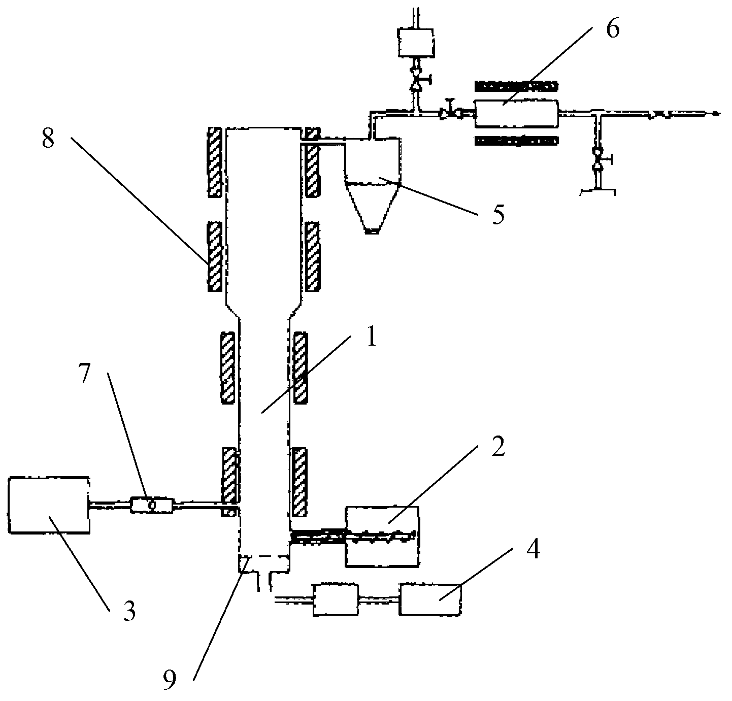
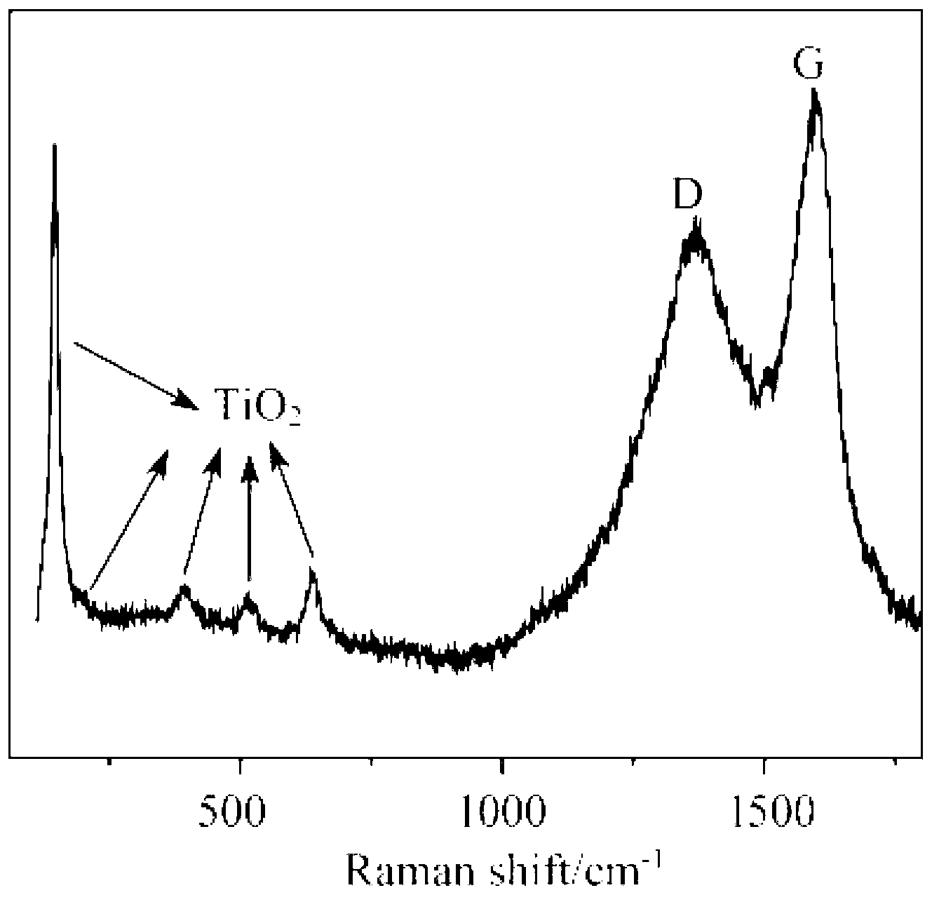
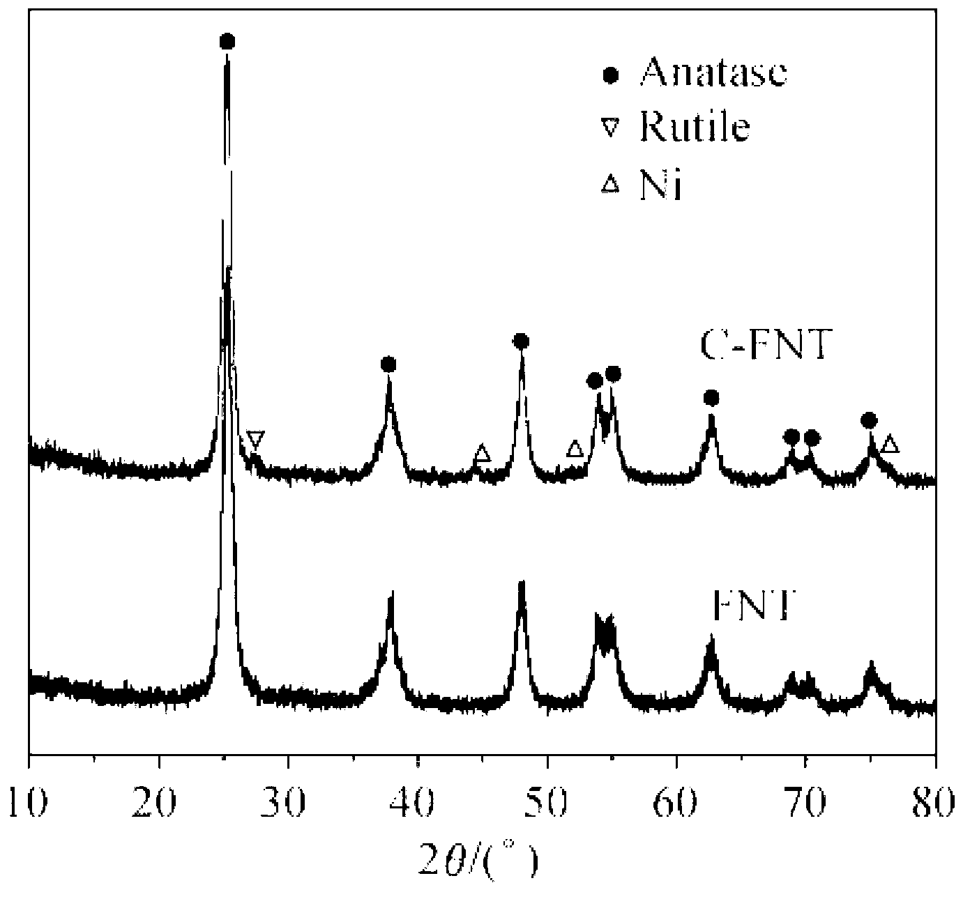

Image

  • Method for preparing fuel gas by burning biomass
  • Method for preparing fuel gas by burning biomass
  • Method for preparing fuel gas by burning biomass

Examples


preparation example Construction

[0051] The preparation of the calcined dolomite catalyst is as follows: crush the dolomite, screen out particles with a particle size of 0.3-0.45 mm, and calcinate at a temperature of 900° C. for 4 hours.

[0052] The carbon nanotube (CNT) grafted Fe-NiO / TiO 2 The concrete preparation method of catalyst is as follows:

[0053] The first step, Fe-NiO / TiO 2 Preparation of catalyst, weigh 68g tetrabutyl titanate solution, add 377mL absolute ethanol and 26.75g nitric acid, stir to obtain solution A; 0.404gFe(NO 3 ) 3 9H 2 O,2.619g Ni(NO 3 )2·6H 2 O was dissolved in 215mL deionized water to obtain solution B. Add solution B dropwise to solution A, stir for 2h, let stand for 20h, and dry at 120°C. Raise the temperature to 500°C at a rate of 3°C / min, and roast for 3h. Preparation Fe-NiO / TiO 2 ;

[0054] In the second step, take the prepared Fe-NiO / TiO 2 10g is placed in a fluidized bed reactor, and the nitrogen flow rate is adjusted to 5L / min to fluidize the catalyst. The te...

Embodiment 1

[0063] The preparation of embodiment 1 calcined dolomite

[0064] Crush the dolomite, screen out particles with a particle size of 0.3-0.45mm, and calcinate at 900°C for 4 hours to obtain the product.

Embodiment 2

[0065] Example 2 Fe-NiO / TiO grafted with carbon nanotubes (CNT) 2 Catalyst preparation

[0066] The surface characteristics of the catalyst were analyzed by ASAP2010 specific surface and pore size analyzer (Micrometrics).

[0067]Weigh 68g tetrabutyl titanate solution, add 377mL absolute ethanol and 26.75g nitric acid, stir to obtain solution A; 0.404gFe(NO 3 ) 3 9H 2 O,2.619g Ni(NO 3 ) 2 ·6H 2 O was dissolved in 215mL deionized water to obtain solution B. Add solution B dropwise to solution A, stir for 2h, let stand for 20h, and dry at 120°C. Raise the temperature to 500°C at a rate of 3°C / min, and roast for 3h. Preparation Fe-NiO / TiO 2 , the prepared Fe-Ni / TiO 2 The comparative area is 63.0m 2 / g, take the prepared Fe-NiO / TiO 2 Put 10g of catalyst in a fluidized bed reactor, adjust the flow rate of nitrogen gas to 5L / min to fluidize the catalyst. Raise the temperature to 500°C, and after the temperature in the reactor is stabilized, feed acetylene gas into the reac...


PUM

PropertyMeasurementUnit
Particle sizeaaaaaaaaaa
Specific surface areaaaaaaaaaaa

Abstract

The invention provides a method for preparing fuel gas by burning biomass. The method comprises the following steps of: firstly, smashing, namely smashing a biomass reaction material; secondly, gasifying, namely gasifying the smashed biomass reaction material to generate synthesis gas; thirdly, primarily purifying, namely removing particulate matter, acidic gas and tar in the synthesis gas obtained by the step two; fourthly, deeply purifying, namely removing sulphide in the synthesis gas obtained by primary purification; fifthly, carrying out methanation, namely carrying out methanation on the synthesis gas purified by the step four to obtain fuel gas; and sixthly, improving quality of gas, namely removing saturated steam, CO2 and unreacted H2 and N2 in the fuel gas subjected to methanation. By adopting the method, two different catalysts are used, so that content of tar produced by burning the biomass is reduced, and gas production rate is increased.

Description

technical field [0001] The invention relates to the technical field of gas preparation, in particular to a method for preparing gas by burning biomass. Background technique [0002] Energy is the material basis for human survival and development. It is an important guarantee for the country's economic and social development. With the development of human society, energy consumption continues to increase. At present, the world's energy consumption is mainly based on non-renewable fossil energy such as coal, oil and natural gas. According to the forecast of the World Energy Organization, the global primary energy demand will increase by 55% between 2005 and 2030, with an average annual growth rate of 1.8%. Energy demand will reach 25.3 billion tons of standard coal. Fossil fuels will remain the main source of primary energy, accounting for 84% of the total increase in energy demand between 2005 and 2030. Due to the sustained and rapid economic development, my country's en...

Claims


Application Information

Patent Timeline
IPC IPC(8): C10L3/08C10L3/10C10J3/46C10J3/54C10J3/84C10K1/00C10K1/02C10K1/04B01J23/755
CPCY02P20/52
Inventor 薛文龙
Owner 青岛新奥胶城燃气有限公司
Learn More