Permanent-magnet slip transmission mechanism

A technology of transmission mechanism and slip difference, which is applied in the direction of electromechanical transmission, generator/motor, electromechanical device, etc., can solve the problems of large volume, complex system mechanism, large system volume, etc., and achieve the effect of small volume and simplified system structure

Inactive Publication Date: 2015-07-15
NANJING INST OF TECH
View PDF7 Cites 0 Cited by
  • Summary
  • Abstract
  • Description
  • Claims
  • Application Information

AI Technical Summary

Problems solved by technology

[0002] There are hydraulic torque converters and hydraulic couplings for transmission components with speed difference between input and output components. Although the system runs smoothly with hydraulic transmission, the machining accuracy is high, the efficiency is low under the condition of large speed difference, and the volume Larger, the structure of the car is a combination of a hydraulic torque converter and a planetary gear row. The characteristics of the hydraulic torque converter are used to realize the stepless speed change when the speed ratio changes in a small range. In order to improve the system efficiency and expand the transmission ratio range, using multiple planetary gear sets to expand its range of speed ratios. According to reports, each additional gear of this type of transmission can save 3% of fuel consumption. At present, its fuel consumption is higher than that of cars equipped with manual transmissions, and the gears are increased. Afterwards, the system mechanism is complicated, and the design and installation are difficult. According to reports, there are even two-shaft automatic transmissions, which obviously make the system larger
Since permanent magnet transmission has the characteristics of non-contact transmission, it has become more and more widely used with the improvement of rare earth permanent magnet technology. At present, there have been many application reports of permanent magnet couplings and permanent magnet couplers, which mainly solve sealing problems and Shaft alignment problem, and in the case of irregular slip transmission, the heat dissipation problem is relatively large. At present, there is no mechanism specially used for slip transmission. If it can be made into a slip transmission mechanism, it can partially replace hydraulic power. torque converter with significantly reduced size and weight

Method used


Image

  • Permanent-magnet slip transmission mechanism
  • Permanent-magnet slip transmission mechanism
  • Permanent-magnet slip transmission mechanism

Examples


Embodiment Construction

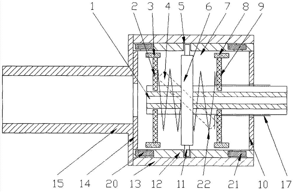
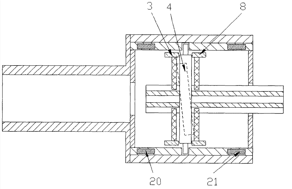
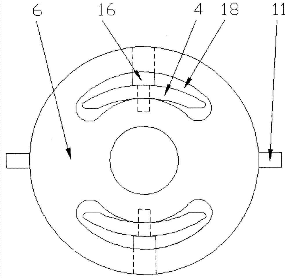
[0023] Refer to attached figure 1 ~ attached Figure 8 , the structural characteristics of a permanent magnet slip transmission mechanism are (as attached figure 1 ~ attached figure 2 ): attached figure 1 For the state of transmitting the maximum torque, the attached figure 2 For the state of no torque transmission or negligible torque transmission, the size of the base plate 6 is 120mm in diameter, the size of the pin 11 is 6mm, the inner diameter of the groove tube 13 is 122mm, the outer diameter is 136mm, the width of the groove 5 is 6mm, and the depth is 5mm 10 pieces of NdFeB permanent magnets are installed on the fourth disk 14, the first disk 2, the second disk 9 and the third disk 10, the number can be adjusted according to the actual size, and the size of the NdFeB permanent magnet is 20mm×20mm× 5mm, the first magnet 3, the second magnet 8, the third magnet 20 and the fourth magnet 21 are tile-shaped magnets with a width of 10mm, attached image 3 For the in...


PUM


Abstract

The invention relates to a permanent-magnet slip transmission mechanism with a slip transmission function. The permanent-magnet slip transmission mechanism structurally comprises a grooved drum provided with two magnetic disks and a groove, a base disk connected with the two magnetic disks through a spring, two pairs of radial-flux magnets, an operating lever and two levers; a torque can be reliably and stably transferred during slip transmission; and the value of the transferred torque can be changed in a stepless manner. The permanent-magnet slip transmission mechanism comprises the base disk 6, the grooved drum 13, the magnetic disk 14, the magnetic disk 10, the magnetic disk 2, the magnetic disk 9, the levers 4, the operating lever 17, and the like, and is suitable for the fields of vehicles, wind power generation systems, air vehicles, machine tools, general machinery, industrial and mineral machinery, engineering machinery, and the like.

Description

technical field [0001] The invention relates to a permanent magnet slip transmission mechanism, which transmits torque when the input element and the output element have a rotational speed difference; the permanent magnetic force interaction of the axial magnetic flux is used to make the input element and the output element non-contact , the axial distance between the disks installed on the base plate can be changed steplessly, and the torque transmitted by the mechanism can be changed steplessly; using the groove on the groove cylinder and the pin on the base plate, the groove plate can slide axially, The magnetic force acts on the disks on both sides respectively, so that when the input element and the output element have a speed difference, the torque can be transmitted reliably in the forward direction, and the generation of reverse torque can be suppressed; magnets with radial magnetic flux are set on the grooved cylinder and the disk of the base plate , and the permanent...

Claims


Application Information

Patent Timeline
Patent Type & Authority Patents(China)
IPC IPC(8): H02K51/00H02N11/00
Inventor 邹政耀张日波胡恒亮
Owner NANJING INST OF TECH
Why Eureka
Try Eureka