Method for implementing bandstop filter with tunable bridge
An implementation method and filter technology, applied in impedance networks, electrical components, multi-terminal-pair networks, etc., can solve the problems of single implementation method, complex structure, poor reliability, etc., and overcome the problems of single implementation method, small size, and channel insertion loss. small effect
- Summary
- Abstract
- Description
- Claims
- Application Information
AI Technical Summary
Problems solved by technology
Method used
Image
Examples
Embodiment 1
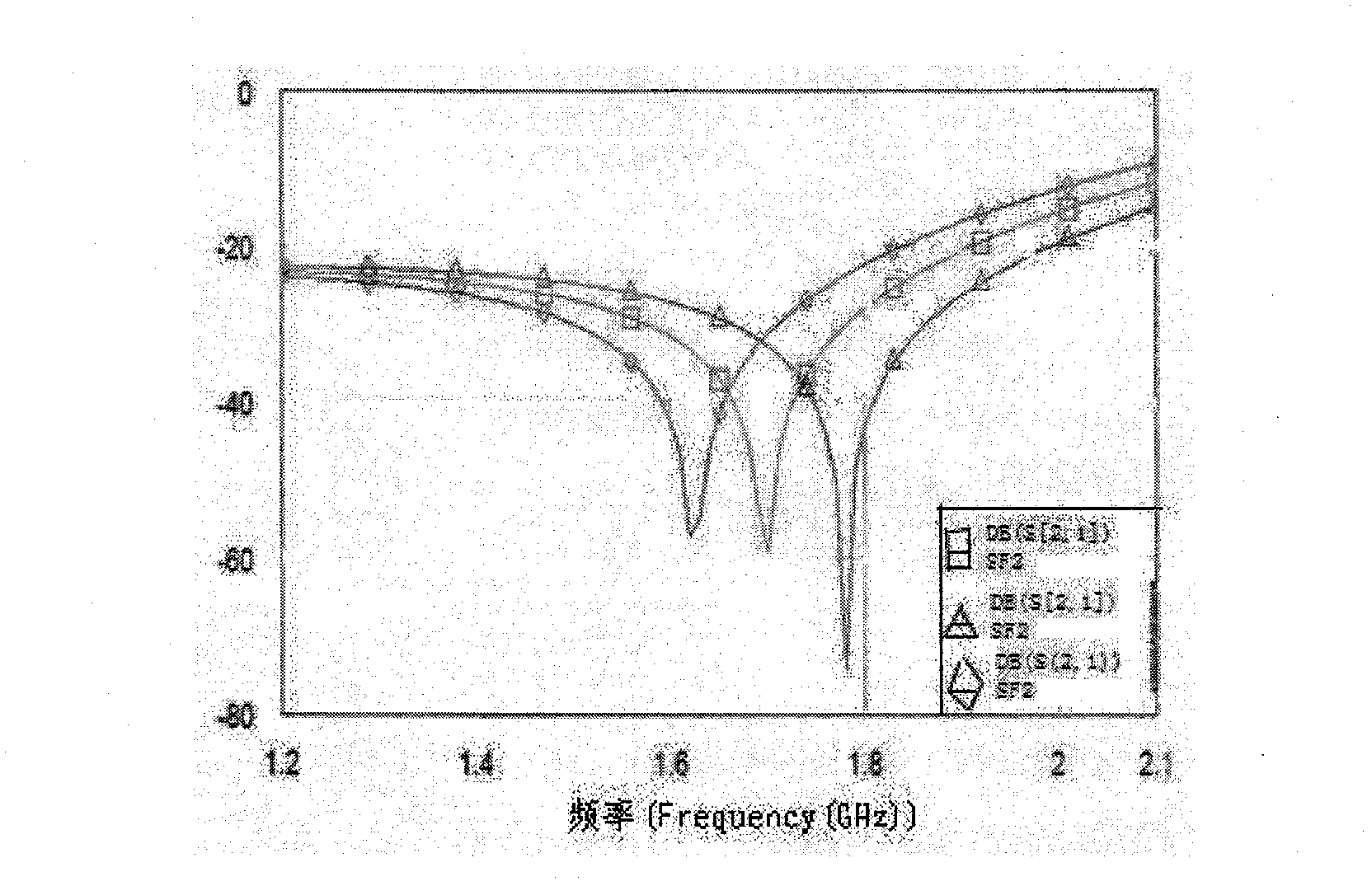
[0013] The center frequency of the designed filter is 1.78GHz, the bandwidth is 1Hz, the characteristic impedance of the input and output feeder is 50Ω, and the insertion loss of the filter is 0.04dB.
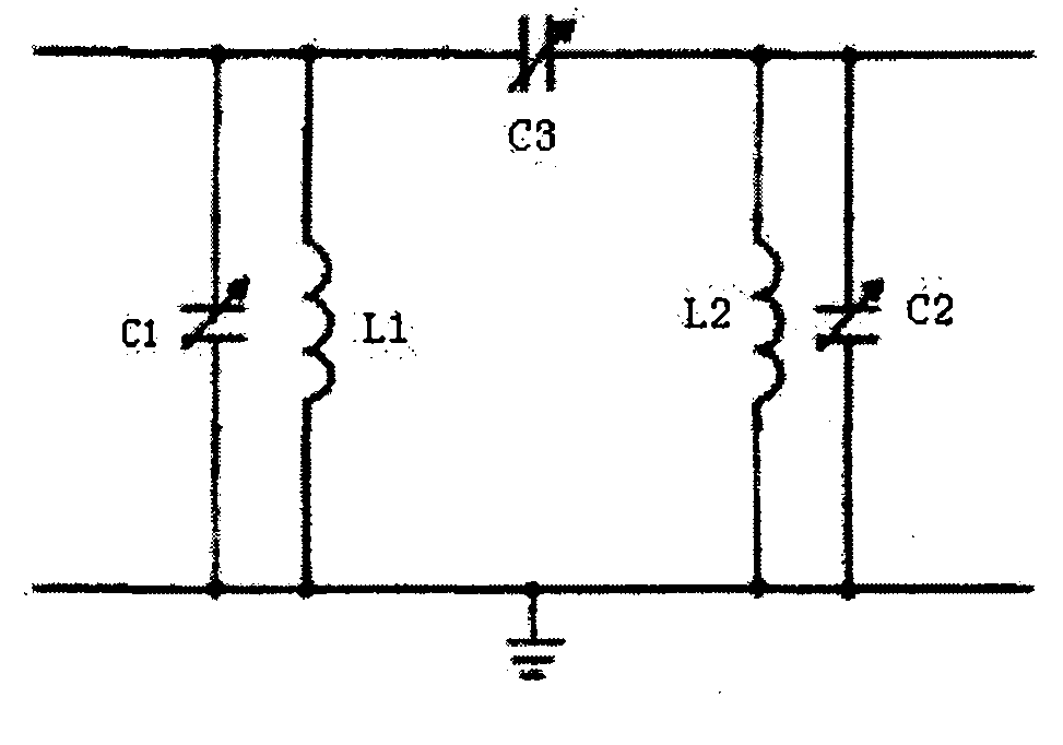
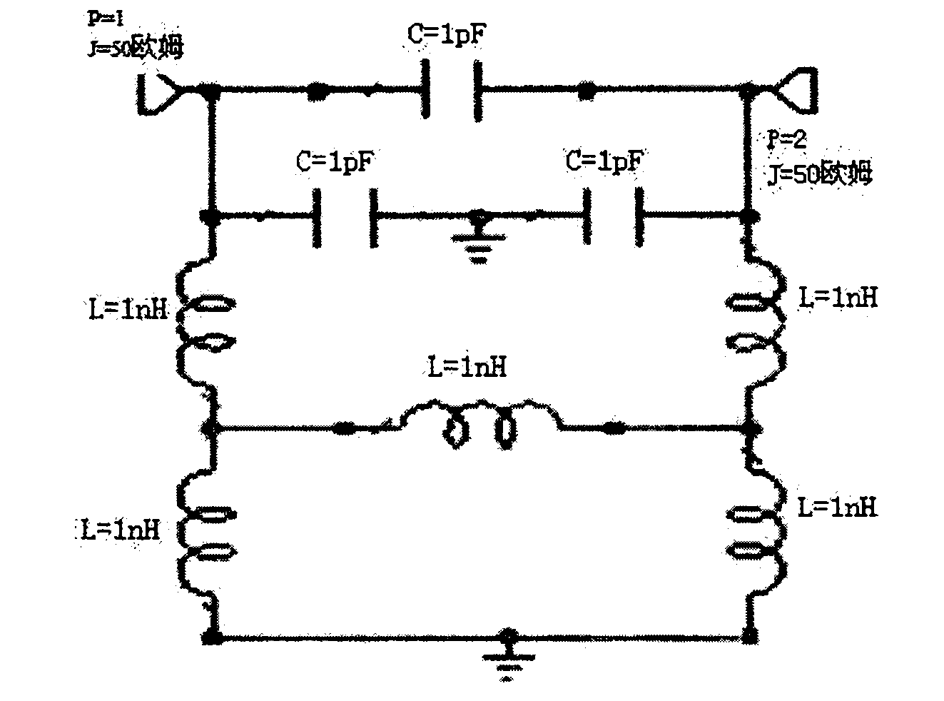
[0014] All capacitance values are 1pF, inductance values are 1nH, and the bridge capacitances are realized with varactors respectively. The circuit of the designed lumped element filter can be obtained as figure 2 As shown, when its bandwidth is fixed, the filter performance with adjustable center frequency is as image 3 shown, from image 3 It can be seen that the band-stop filter can be adjusted by using the bridge method, which fully meets the design performance requirements.
[0015] The designed adjustable bridge band-stop filter has been successfully used in a pulsed multi-channel receiver. After FSK modulation and demodulation, the output is good. The results of use show that the device has a good degree of suppression to the modulation pulse and noise level of ...
PUM
 Abstract
Description
Claims
Application Information
 - R&D
- Intellectual Property
- Life Sciences
- Materials
- Tech Scout
- Unparalleled Data Quality
- Higher Quality Content
- 60% Fewer Hallucinations
Browse by: Latest US Patents, China's latest patents, Technical Efficacy Thesaurus, Application Domain, Technology Topic, Popular Technical Reports.
© 2025 PatSnap. All rights reserved.Legal|Privacy policy|Modern Slavery Act Transparency Statement|Sitemap|About US| Contact US: help@patsnap.com


