
Riding wheel transmission mechanism

A technology of transmission mechanism and supporting wheel, which is applied in the direction of grinding drive device, grinding machine tool parts, metal processing equipment, etc., can solve the problem of inability to meet the processing requirements of workpieces and machine tools, the inability to meet the strength requirements of supporting wheel components, and the quality of piston rods. Large and other problems, to achieve the effect of smooth transmission, long life and large transmission power

Inactive Publication Date: 2013-07-31
CHONGQING HENGSHAN MACHINERY +1
View PDF6 Cites 5 Cited by
  • Summary
  • Abstract
  • Description
  • Claims
  • Application Information

AI Technical Summary

Problems solved by technology

At this time, the calculated distance between the supporting wheels is only 300mm, so the size of the transmission shaft of the universal joint mechanism must be small. Unable to meet the strength requirements that the supporting wheel assembly should have
Therefore, the existing transmission device cannot meet the processing requirements of the workpiece and the machine tool due to its own defects when transmitting workpieces with a small length-diameter ratio and high mass.

Method used


Image

  • Riding wheel transmission mechanism
  • Riding wheel transmission mechanism
  • Riding wheel transmission mechanism

Examples


Embodiment Construction

[0027] The present invention will be further described below in conjunction with the drawings and embodiments:

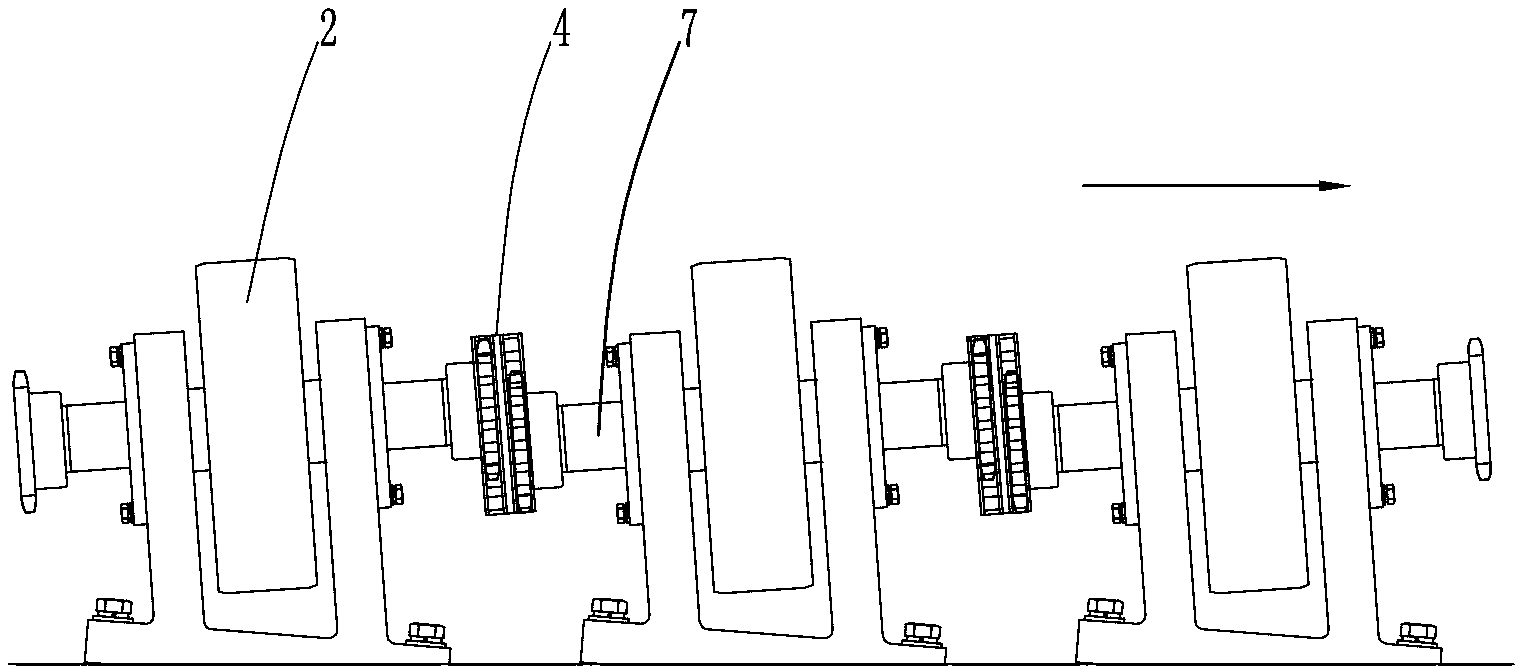
[0028] Such as Figure 1-Figure 4 As shown, the present invention includes a rack 1, and the structure of the rack 1 is in the prior art, which will not be repeated here. On the left and right sides of the upper end of the frame 1, there are two rows of supporting wheels distributed in the axial direction, one of which is the driven supporting wheel 3 and the other is the driving supporting wheel 2. The structure and installation method of the follower roller 3 are in the prior art, and will not be repeated here. The driving roller 2 is sleeved in the middle of the main shaft 7 and is supported on the roller seat 9 by the main shaft 7. The bottom surface of the supporting wheel base 9 is a flat surface, and an inclination adjusting device 8 is provided between the supporting wheel base 9 and the frame 1. The inclination adjusting device 8 consists of a bottom plate 1...


PUM


Abstract

The invention discloses a riding wheel transmission mechanism which comprises a frame (1), wherein two rows of riding wheels are arranged at the upper part of the frame (1) in parallel; one row is drive riding wheels (2), and the other row is follow-up riding wheels (3); the drive riding wheels (2) are sleeved on a principal shaft (7); chain wheels (6) are correspondingly sleeved at the front and the back end of the principal shaft (7); a double-row gear (17) of a motor (5) is directly meshed with two chain wheels (6) between two adjacent drive riding wheels (2); and two chain wheels (6) between two adjacent drive riding wheels (2) in other positions are connected through double-chains (4). Through the adoption of the structure that the double-row gear of the motor is directly meshed with the corresponding chain wheels; and the two chain wheels between two adjacent drive riding wheels (2) in other positions are connected through the double-chains, the riding wheel transmission mechanism has the advantages that the equable transmission of the workpiece with small draw ratio and high quality is realized; and production efficiency can be adjusted and optimized by arranging a gradient adjusting device between a riding wheel base and the frame.

Description

Technical field [0001] The invention belongs to the technical field of mechanical manufacturing, and specifically relates to a supporting wheel transmission mechanism. Background technique [0002] The supporting wheel assembly is one of the important components of equipment such as centerless external belt grinder. When the supporting wheel assembly is working, it can drive the workpiece to rotate around its own axis and provide power for the axial feed of the workpiece. Common supporting wheel transmission devices include universal joint transmission mechanism, synchronous belt transmission mechanism, gear transmission mechanism and so on. There is no problem in the transmission of general workpieces by the above-mentioned transmission device, but when the workpiece with a relatively small length and a larger mass is transmitted, the continued use of the above three traditional transmission devices will cause the problem that the surface quality of the workpiece cannot meet th...

Claims


Application Information

Patent Timeline
Patent Type & Authority Applications(China)
IPC IPC(8): B24B47/10
Inventor 李代建黄云杨俊峰李忠程荣凯
Owner CHONGQING HENGSHAN MACHINERY
Learn More