
A pneumatic clamping system for thin-walled pipes

A thin-walled pipe and pipe technology, applied in applications, household appliances, tubular objects, etc., can solve the problems of uneven clamping force and low clamping accuracy of three-jaw chucks, and achieve good processing accuracy and precise clamping force. , good flexibility

Active Publication Date: 2016-01-27
KUNSHAN THETA MICRO
View PDF11 Cites 0 Cited by
  • Summary
  • Abstract
  • Description
  • Claims
  • Application Information

AI Technical Summary

Problems solved by technology

[0005] In order to solve the above problems, the object of the present invention is to provide a pneumatic clamping system suitable for thin-walled pipes, so as to solve the problems of low clamping accuracy and uneven clamping force of three-jaw chucks when clamping small diameter pipes

Method used


Image

  • A pneumatic clamping system for thin-walled pipes
  • A pneumatic clamping system for thin-walled pipes
  • A pneumatic clamping system for thin-walled pipes

Examples


Embodiment Construction

[0018] In order to make the object, technical solution and advantages of the present invention clearer, the present invention will be further described in detail below in conjunction with the accompanying drawings and embodiments. It should be understood that the specific embodiments described here are only used to explain the present invention, not to limit the present invention.

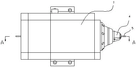
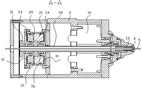
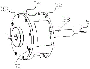
[0019] Please refer to Figure 1 to Figure 3 As shown, the pneumatic clamping system applicable to thin-walled pipes of the present invention includes an air pressure control circuit (not shown), a rotating shaft module 1, a piston module arranged at one end of the rotating shaft module 1, and a piston module arranged inside the rotating shaft module 1. The tie rod module and the chuck 4 arranged at the other end of the rotating shaft module 1 , the chuck 4 clamps the pipe 5 .

[0020] Wherein, the rotating shaft module 1 is set to be hollow, allowing the pull rod 38 to pass through the middle. A...


PUM


Abstract

The invention discloses a pneumatic clamping system applicable to thin-walled tubes. The pneumatic clamping system comprises a pneumatic pressure control loop, a rotary shaft module, a piston module, a pull rod module and a clamping head, wherein the piston module is arranged at one end of a rotary shaft, the pull rod module is arranged inside the rotary shaft, and the clamping head is arranged at the other end of the rotary shaft. According to the pneumatic clamping system applicable to the thin-walled tubes, disclosed by the invention, the self adaptability is strong, the flexibility is good, and the tubes of different tube diameters can be clamped; a precise clamping force can be provided, and the clamping force is uniform; shown by customer verification, the machining accuracy is good and can reach below + / -3 microns; a tube can be smoothly clamped into a clamping head hole by the tube clamping head; during cutting, the tube is clamped tightly by a pneumatic clamping force; and when the feeding is required, a clamping mechanism is unclamped through only putting through pressure gas, so that the feeding can be carried out smoothly, the whole process can be completed in several seconds, and the repeatable accuracy reaches below + / -2 microns.

Description

technical field [0001] The invention belongs to the technical field of laser fine processing of thin-walled pipes, and in particular relates to a pneumatic clamping system suitable for thin-walled pipes. Background technique [0002] Due to the simple process and fast speed, laser cutting has the characteristics of small slit width, good incision parallelism, small surface roughness, high dimensional accuracy, small workpiece deformation and heat-affected zone, no mechanical stress and surface damage, etc., and can accurately cut shapes Complex micro-parts have thus become the main processing method used in the field of micro-machining of thin-walled pipes. [0003] In the existing tube laser processing equipment, most of the tubes are clamped by a three-jaw chuck, and more than three jaws are evenly distributed on a circumference, and these jaws are moved to the center at the same time by mechanical or electric means. Provide a way to clamp the pipe. When this clamping ...

Claims


Application Information

Patent Timeline
Patent Type & Authority Patents(China)
IPC IPC(8): B23K26/70B23K37/053B23K26/38B23K101/06
Inventor 魏志凌宁军夏发平马秀云
Owner KUNSHAN THETA MICRO
Learn More