
Solid-liquid separation sewage treatment device

A sewage treatment device and solid-liquid separation technology, applied in the direction of water/sewage multi-stage treatment, water/sludge/sewage treatment, chemical instruments and methods, etc. Level processing technical advantages and other issues to achieve the effects of reducing work interference, facilitating digestion, and stabilizing process effects

Inactive Publication Date: 2013-07-17
赵峰
View PDF0 Cites 2 Cited by
  • Summary
  • Abstract
  • Description
  • Claims
  • Application Information

AI Technical Summary

Problems solved by technology

[0002] The essence of sewage treatment is solid-liquid separation in water. Sludge is a by-product of sewage treatment. Anaerobic degradation of sludge will produce digested gas. The flotation of digested gas disturbs the precipitation of organic matter in water. In conventional anaerobic In the treatment process, the digestive juice is mixed with the sludge bacteria, and the decomposition products of the accumulated sludge will release organic matter into the water body, which affects the effect of sewage treatment
Multi-stage sewage treatment can intercept pollutants and impurities step by step, and improve the sewage step by step. If sludge accumulates and decomposes to release organic matter, the accumulated sludge will weaken the technical advantages of multi-stage sewage treatment

Method used


Image

  • Solid-liquid separation sewage treatment device
  • Solid-liquid separation sewage treatment device
  • Solid-liquid separation sewage treatment device

Examples


Embodiment Construction

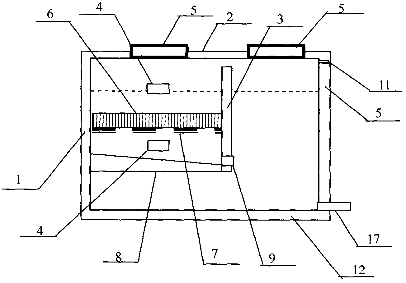
[0024] Such as figure 1 , 3 , 4, 5, 6, and 7 shown embodiment one is that a front end has a settling tank 18 in series with three solid-liquid separation treatment unit sewage treatment units, each solid-liquid separation treatment unit is separated by muddy water inside the bottom plate 8 and muddy water The partition side wall plate 3 is divided into a sewage treatment space and a sludge treatment space. In the sewage treatment space, there is a sewage interception device 6. At least one air-blocking sedimentation pipe 10 is installed on the mud-water separation bottom plate 8. The upper surface slope of the mud-water separation bottom plate 8 To the upper opening 13 of the air-blocking sedimentation pipe 10, the lower opening 14 of the air-blocking sedimentation pipe 10 is lower than the bottom of the mud-water separation bottom plate 8, and the side walls of the corresponding two sides of the sewage treatment space are respectively provided with water holes 4, respectively...


PUM


Abstract

The invention provides a solid-liquid separation sewage treatment device which is characterized in that the sewage treatment device comprises a deposition tank positioned on the front end and connected in series with three solid-liquid separation treatment units. Each Solid-liquid separation sewage treatment device is divided into a sewage treatment space and a sludge treatment space by using a sludge-sewage separation bottom plate 8 and a sludge-sewage separation side wall plate 3. An interception device 6 is arranged in the sewage treatment space. At least one deposited sludge side discharge port 9 is arranged at the lower part of the sludge-sewage separation side wall plate 3. The upper surface of the sludge-sewage separation bottom plate 8 is inclined to the deposited sludge side discharge port 9. Rinsing ports 4 are respectively provided on side walls on the two sides corresponding to the sewage treatment space, and are positioned on the side walls above or below the interception material or device 6. Inspection ports 5 are provided on the top plate of the tank bodies of the sewage treatment space and the sludge treatment space. A ventilation hole (pipe) 11 is provided on the upper part of the side wall. With the device and the method, sewage treatment and sludge treatment can be separated, such that the influence on sewage treatment caused by digestion gas and sludge degradation products is reduced, and sewage treatment and sludge reduction treatment can be realized simultaneously.

Description

technical field [0001] The invention relates to a sewage treatment device. Background technique [0002] The essence of sewage treatment is solid-liquid separation in water. Sludge is a by-product of sewage treatment. Anaerobic degradation of sludge will produce digested gas. The flotation of digested gas disturbs the precipitation of organic matter in water. In conventional anaerobic During the treatment process, the digestive juice is mixed with the sludge bacteria, and the decomposition products of the accumulated sludge will release organic matter into the water body, which affects the effect of sewage treatment. Multi-stage sewage treatment can intercept pollutants and impurities step by step, and improve the sewage step by step. If sludge accumulates and decomposes to release organic matter, the accumulated sludge will weaken the technical advantages of multi-stage sewage treatment. The core of sewage treatment is to separate impurities from the water body, while the ...

Claims


Application Information

Patent Timeline
Patent Type & Authority Applications(China)
IPC IPC(8): C02F9/14
Inventor 赵峰
Owner 赵峰
Learn More