
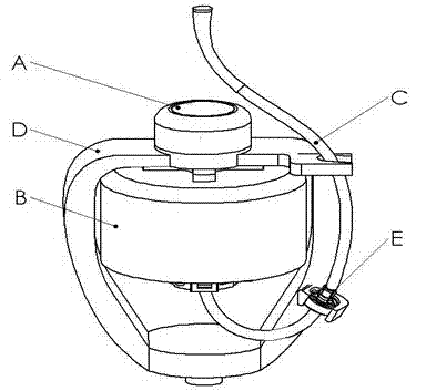
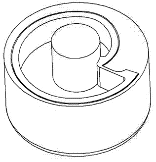
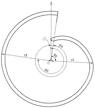
Structure of a separating disk used for blood continuous centrifugal separation

A technology of centrifugal separation and separation disc, which is applied in centrifuges, blood circulation processing, etc., to achieve the effect of improving safety factor, efficient continuous collection, and improving separation efficiency

Active Publication Date: 2013-07-10
金卫医疗科技(上海)有限公司
View PDF7 Cites 2 Cited by
  • Summary
  • Abstract
  • Description
  • Claims
  • Application Information

AI Technical Summary

Problems solved by technology

Although the latter is more ingenious in the design of the hard chassis and the separate soft bag, and has a certain effect in practice, there is still room for improvement in the design

Method used


Image

  • Structure of a separating disk used for blood continuous centrifugal separation
  • Structure of a separating disk used for blood continuous centrifugal separation
  • Structure of a separating disk used for blood continuous centrifugal separation

Examples


Embodiment 1

[0052] In this embodiment, the separation chamber 6 is composed of the outer separation cylinder 4 and the inner separation cylinder 5. The outer side wall of the outer separation cylinder has a radius of 220 mm. The curve projected on the surface of the inner chamber wall of the outer separation cylinder on the vertical plane of the rotation axis is:

[0053]

[0054] The outer side wall of the inner separation cylinder and the inner cavity wall of the outer separation cylinder have the same curved surface form, and the distance between the projection curves of the two on the plane perpendicular to the rotation axis is 7 mm.

[0055] The bottom end of the outer wall of the inner separation cylinder is provided with a protruding portion extending radially, and its cross-sectional structure in the axial direction is as follows: Figure 9 As shown, the radial width of the raised portion is c=6mm, and the axial height is h=2mm. One side of the raised portion coincides with the ...

Embodiment 2

[0058] In this embodiment, the separation cavity is composed of an outer separation cylinder and an inner separation cylinder. The outer wall of the outer separation cylinder has a radius of 220 mm. The curve projected on the surface of the inner cavity wall of the outer separation cylinder on a plane perpendicular to the rotation axis is:

[0059]

[0060]The curve projected on the plane perpendicular to the axis of rotation on the outer wall of the inner separation cylinder is:

[0061]

[0062] The bottom end of the outer wall of the inner separation cylinder is provided with a protruding portion extending radially, and its cross-sectional structure in the axial direction is as follows: Figure 9 As shown, the radial width of the raised portion is c=6mm, and the axial height is h=2mm. One side of the raised portion coincides with the extension surface of the bottom surface of the inner separation cylinder, and the other side is formed by a circle with a radius of r=16m...


PUM


Abstract

The invention relates to a structure of a separating disk used for blood continuous centrifugal separation. The separating disk comprises an inner separating cylinder and an outer separating cylinder, the inner separating cylinder is coaxially fixed inside the inner chamber of the outer separating cylinder, the inner chamber wall of the outer separating cylinder is in a curved surface form, the outer lateral wall of the inner separating cylinder is the same with or not the same with the curved surface form of the inner chamber wall of the outer separating cylinder, the separating lacuna of a separating disk is reserved between the inner chamber wall of the outer separating cylinder and the outer lateral wall of the inner separating cylinder, the separating lacuna adopts a curved surface body structure in which a disposable separating soft bag is accommodated. In the invention, the separating disk structure for blood continuous centrifugal separation is simplified, the mounting of the separating soft bag is enabled to be more simple and convenient, and the use is safer.

Description

technical field [0001] The present invention relates to blood centrifugal separation technology, in particular to a separation disk for continuous centrifugal separation of blood, used in conjunction with a disposable separation soft bag, which can more easily reflect the advantages of differential centrifugal separation and improve the working efficiency of automatic apheresis of blood components . Background technique [0002] Whether it is scientific research, medical clinical practice or industrial production, and more occasions, it is necessary to separate blood, such as separating a single component from whole blood, usually using centrifugation to separate various single components from blood for use Clinical treatment, scientific research or preparation of raw materials and other occasions. The most common method is to separate red blood cells, granulocytes, monocytes, platelets, and plasma from whole blood through a centrifuge system, or wash thawed frozen red ...

Claims


Application Information

Patent Timeline
Patent Type & Authority Applications(China)
IPC IPC(8): B04B7/08B04B5/04A61M1/36
Inventor 经建中唐海波刘继纯陆永建
Owner 金卫医疗科技(上海)有限公司
Learn More