Polyethylene steel and plastic composite winding pipe

A steel-plastic composite and polyethylene technology, applied in the direction of pipes, rigid pipes, pipes/pipe joints/fittings, etc., can solve the problems of low creep, heavy weight, easy leakage, etc., and achieve improved corrosion resistance. The level of resistance to internal pressure and the effect of facilitating construction and installation

Inactive Publication Date: 2013-07-03
福建亚通新材料科技股份有限公司
View PDF5 Cites 1 Cited by
  • Summary
  • Abstract
  • Description
  • Claims
  • Application Information

AI Technical Summary

Problems solved by technology

[0002] At present, cement pipes and metal pipes are still the main products of large-diameter water supply and drainage pipes. The advantage is that cement pipes and metal pipes can still maintain high rigidity requirements under larger diameters, but the disadvantages are more prominent, mainly because they are not corrosion-resistant and easy to Leakage, heavy weight, difficult construction, etc. For plastic materials, due to their own creep and low modulus, their application in the field of large-diameter pipes is greatly restricted, especially large-diameter pipes. Caliber water supply pipes, such as water supply pipes with a diameter of 2000mm or more, are basically not available in plastic pipes. To use plastic pipes to achieve the purpose of large-diameter water supply and drainage requires a large amount of raw material resources, which is not in line with the national policy of saving energy and reducing energy consumption.

Method used


Image

  • Polyethylene steel and plastic composite winding pipe
  • Polyethylene steel and plastic composite winding pipe

Examples


Embodiment Construction

[0011] Preferred embodiments of the present invention will be described in detail below in conjunction with the accompanying drawings.

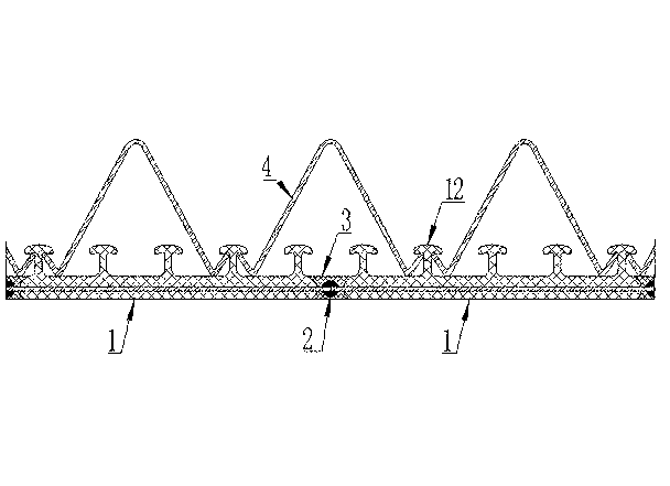
[0012] Such as figure 1 As shown, the pipe body of the polyethylene steel-plastic composite winding pipe is formed by winding the steel-plastic composite board strip 1, and the adjacent steel-plastic composite board strips 1 are welded by metal electric welding process, and the polyethylene resin coating layer 3 is wrapped on the welding line 2 between the adjacent steel-plastic composite plate strips 1, and the V-shaped reinforced steel ribs 4 rolled by galvanized steel strips are embedded between the T-shaped caps 12 on the outer wall of the pipe.

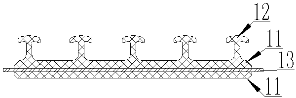
[0013] Such as figure 2 As shown, the main body of the steel-plastic composite board strip 1 is a flat wall structure of a polyethylene matrix. Four T-shaped caps 12 are arranged on the upper side of the flat wall 11. The lower side of the flat wall 11 is smooth, and a layer of steel is arrang...


PUM

PropertyMeasurementUnit
diameteraaaaaaaaaa

Abstract

The invention relates to a polyethylene steel and plastic composite winding pipe. A pipe body of the composite winding pipe is wound and formed by steel and plastic composite plate belt materials, the adjacent steel and plastic composite plate belt materials are welded by adopting a metal welding process, a polyethylene resin covering layer is covered on a welding line between the adjacent steel and plastic composite plate belt materials, and V-shaped reinforced steel ribs are wound and embedded between T-shaped caps arranged at the outer wall of the pipe body. The pipe body of the polyethylene steel and plastic composite winding pipe is wound and formed by the steel and plastic composite plate belt materials, the complete pipe is welded by the steel belts inside the pipe wall to be used as the internal pressure resistance support pipe, the internal pressure resistance level of a large-caliber plastic pipe is greatly improved, meanwhile, compared with a plastic pipe, the polyethylene steel and plastic composite winding pipe has higher annular rigidity, the pipe wall of the steel belt welding pipe is completely covered in the polyethylene resin, the corrosion resistance performance is greatly improved, the outer wall adopts the V-shaped reinforced steel bars as a main body for realizing the effect of supporting the external pressure, on the use premise of greatly saving steel and plastics, the annular rigidity of the integral pipe material is greatly improved, in addition, the weight of the integral pipe materials is light, and the construction and the installation are favorably realized.

Description

technical field [0001] The invention belongs to the field of pipe manufacturing, in particular to a polyethylene steel-plastic composite winding pipe. Background technique [0002] At present, cement pipes and metal pipes are still the main products of large-diameter water supply and drainage pipes. The advantage is that cement pipes and metal pipes can still maintain high rigidity requirements under larger diameters, but the disadvantages are more prominent, mainly because they are not corrosion-resistant and easy to Leakage, heavy weight, difficult construction, etc. For plastic materials, due to their own creep and low modulus, their application in the field of large-diameter pipes is greatly restricted, especially large-diameter pipes. Caliber water supply pipes, such as water supply pipes with a diameter of more than 2000mm, are basically not available in plastic pipes. To use plastic pipes to achieve the purpose of large-diameter water supply and drainage requires a la...

Claims


Application Information

Patent Timeline
Patent Type & Authority Applications(China)
IPC IPC(8): F16L9/16
Inventor 陈鹊许盛光陈建福苏敏陈黎星蒋江淮吴亚平
Owner 福建亚通新材料科技股份有限公司
Why Eureka
Try Eureka