Eureka AIR delivers breakthrough ideas for toughest innovation challenges, trusted by R&D personnel around the world.

Continuously wound reinforced corrugated pipe and manufacturing method thereof

A technology of winding reinforcement and manufacturing method, which is applied in the field of continuous winding reinforcement corrugated pipe and its manufacturing, can solve the problems of difficulty in guaranteeing the quality of welded joints, decomposition and fracture of plastic macromolecules, cracking of welded joints of pipes, etc. The effect of improving stability and increasing external surface area

Active Publication Date: 2015-01-14
戴爱清 +1
View PDF6 Cites 11 Cited by
  • Summary
  • Abstract
  • Description
  • Claims
  • Application Information

AI Technical Summary

Problems solved by technology

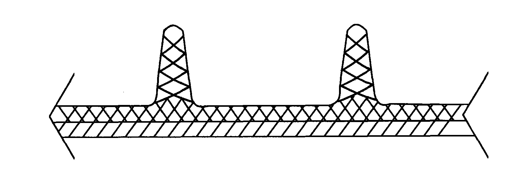
Although the surface of the fins where the flame goes is melted, the high temperature can easily cause the decomposition and fracture of the plastic macromolecules, and the quality of the welded joints is even more difficult to guarantee.
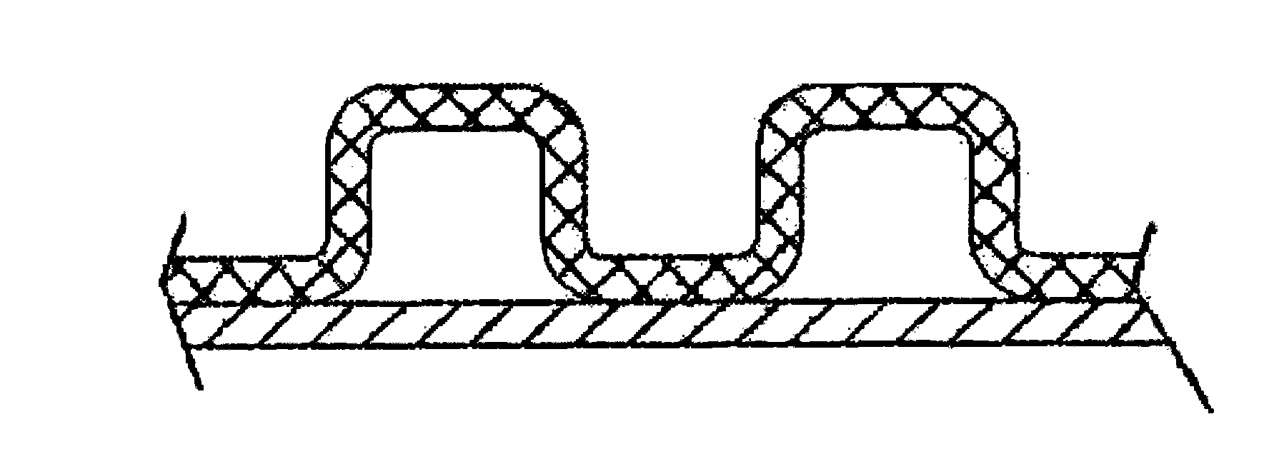
Therefore, in actual use, it can be seen that when these pipes are knocked or partially squeezed during loading, unloading, transportation or construction, it is often easy to cause cracks at the welded joints of the pipes, or spread out and be damaged in the form of a helical spring.

Method used


Image

  • Continuously wound reinforced corrugated pipe and manufacturing method thereof
  • Continuously wound reinforced corrugated pipe and manufacturing method thereof
  • Continuously wound reinforced corrugated pipe and manufacturing method thereof

Examples


Embodiment Construction

[0032] The specific implementation manners of the present invention will be further described in detail below in conjunction with the accompanying drawings and embodiments. The following examples are used to illustrate the present invention, but are not intended to limit the scope of the present invention.

[0033] see Figure 4 , 6 And as shown in 7, a continuous winding reinforced corrugated pipe, comprising a plurality of helically wound special-shaped strips 1 with butt fins 100 on both sides overlapped and fused with each other through the fins 100 to form a continuous solid-walled cylindrical pipe The body, the wall of the cylindrical pipe body is spirally surrounded by a plurality of hollow reinforcing ribs, and each of the hollow reinforcing ribs is provided on the pipe wall of the cylindrical pipe body by reinforcing the adhesive layer 2. A special-shaped single-wall corrugated reinforced pipe 3 and an outer reinforcing layer 4 that spirally surrounds and presses on...


PUM


Abstract

The invention discloses a continuously wound reinforced corrugated pipe and a preparation method thereof. The pipe comprises a continuous solid-wall cylindrical pipe body formed by lapping and fusing a plurality of spirally wound special rods of which the two sides are provided with butting wings through the wings; a plurality of hollow reinforcing ribs are spirally wound on the pipe wall of the cylindrical pipe body; each hollow reinforcing rib comprises at least one special single-wall corrugated reinforcement pipe which is spirally wound on the pipe wall of the cylindrical pipe body through a reinforcement adhesive layer, and an outer reinforcement layer which is spirally wound, spans and presses on the special single-wall corrugated reinforcement pipe and of which two ends are adhered to the pipe wall of the cylindrical pipe body; the center line of each hollow reinforcing rib is overlapped with the center line of a lapping and fusing part of wings of an adjacent special rod. The pipe is high in stability and welding effect, the crest height of the pipe is higher than that of a double-wall corrugated pipe, the continuously wound reinforced corrugated pipe can be produced by matching common wound pipe production equipment with a suitable die, and equipment investment is small.

Description

technical field [0001] The present invention relates to continuous winding reinforced corrugated pipe and its manufacturing method. Background technique [0002] In urban sewer pipes and various sewage pipes, various forms of plastic pipes are used more and more. Because there is usually no pressure in the pipe, in order to improve its resistance to external pressure or impact, plastic pipes with different forms of rib structures on the outer periphery of the pipe wall have been used in many cases. At present, there are several kinds of plastic pipes with this structural form and corresponding preparation methods as follows: a kind of plastic pipes are directly extruded. The most representative ones are double-wall corrugated pipes and circumferentially reinforced pipes formed by direct extrusion. The inner wall layer is a continuous and smooth surface, and the outer wall layer is a hollow corrugated structure or a solid annular rib structure. The axial partial cross-secti...

Claims


Application Information

Patent Timeline
Patent Type & Authority Applications(China)
IPC IPC(8): F16L11/11F16L11/20B29C47/20B29L23/00B29L16/00B29C48/32
CPCB29C48/00B29C53/60B29D23/00B29L2016/00F16L9/16F16L11/11
Inventor 韩云朋
Owner 戴爱清
Why Eureka
Eureka Blog
Learn More