
Method for heating oil shale underground in situ

一种油页岩、原位的技术,应用在油页岩地下原位加热领域,达到避免有毒导电材料、减少施工量的效果

Active Publication Date: 2013-06-26
JILIN UNIV
View PDF9 Cites 19 Cited by
  • Summary
  • Abstract
  • Description
  • Claims
  • Application Information

AI Technical Summary

Problems solved by technology

but requires a lot of electricity to heat

Method used


Image

  • Method for heating oil shale underground in situ

Examples


Embodiment 1

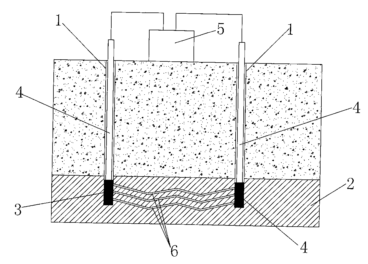
[0023] The experiment was carried out with oil shale samples in the laboratory, and the distance between the electrodes was 50cm. Before the experiment started, the resistance between the electrodes was measured as 250K ohms. During the experiment, an alternating current with a frequency of 50 Hz and a peak voltage of 5 KV was first applied to the electrodes. By visual observation, it can be found that partial discharge phenomenon occurs at this voltage. The power consumption of the power supply is about 300W. This process lasts 30 minutes. During these 30 minutes, a plasma channel of electrothermal breakdown gradually formed. The resistance between the electrodes became 800 ohms. Subsequently, a current with a frequency of 50 Hz will pass between the electrodes, and the resistance heating effect of the low-resistance channel will be used for heating. The guaranteed power is 1KW, and the voltage is also reduced to 100V.

Embodiment 2

[0025] In the laboratory, the lignite sample was used for the experiment, and the distance between the electrodes was 45cm. Before the experiment, the resistance between the electrodes was measured as 150K ohms. At the beginning of the experiment, an alternating current with a frequency of 50 Hz and a peak voltage of 8 KV was first applied to the electrodes. By visual observation, it can be found that partial discharge phenomenon occurs at this voltage. The power consumption of the power supply is about 600W. This process lasts 15 minutes. During these 15 minutes, a plasma channel of electrothermal breakdown gradually formed. The resistance between the electrodes became 300 ohms. Subsequently, a current with a frequency of 50 Hz will pass between the electrodes, using the resistance heating effect of the low-resistance channel for heating. At the beginning, the voltage is hundreds of volts. , In order to ensure that the power is 1KW, the voltage is also reduced to 60V.

...


PUM


Abstract

The invention discloses a method for heating oil shale underground in situ. According to the method, shale oil and fuel gas can be obtained from an underground oil shale seam in situ, and the fuel gas can also be obtained from an underground coal seam in situ. Wells are drilled downwardly from the ground surface, and the drilling depth of each well reaches the inside of an operation region of an underground oil shale ore bed. At least two wells are drilled, and electrodes are placed in the wells. Firstly, high-voltage electricity which is sufficient to cause partial discharge of the oil shale ore bed is conducted into the electrodes, and then a plasma channel is formed in the oil shale ore bed and can be subjected to breakdown by the high-voltage electricity; after the resistance of each of two electrode regions is lowered, the two electrodes are used for conducting currents into the plasma channel in the oil shale ore bed; the oil shale ore bed is heated under the resistance heating function of the plasma channel; and released heat is used for realizing thermal cracking and gasification of fixed organic carbon in the oil shale ore bed. Through the method for heating the oil shale underground in situ, the heating speed of an underground ore bed can be increased, hydraulic fracturing does not need to be carried out on a rock stratum, and the use of poisonous conductive materials is avoided at the same time.

Description

technical field [0001] The present invention relates to a mining technology of oil shale, in particular to a method for underground in-situ heating of oil shale. The method can obtain shale oil and gas fuel in situ from oil shale, i.e. combustible gas, and can also be obtained from coal Obtain combustible gas in situ. Background technique [0002] At present, the known coal or oil shale underground gasification methods are: drilling, penetration, ignition, blowing and extraction of product gas. The disadvantage of this method is that the obtained combustible gas has a lower calorific value. This is due to the fact that a large amount of steady-flow gas will be mixed into the combustible gas when the organic matter is burned in the underground gasification area. This method is disclosed in Russian No. 2385412 patent, and classification number is: МПК E21MB43 / 295. [0003] Another known method is: drilling at least one well to a depth penetrating the working interval of the...

Claims


Application Information

Patent Timeline
Patent Type & Authority Applications(China)
IPC IPC(8): E21B43/241H05B7/00
CPCC10G1/00C10G1/02C10G32/02C10G2300/1033C10G2300/4037E21B43/2401H05B3/60H05B2214/03C10B53/06
Inventor 孙友宏拉帕金.菲拉基米尔韩炜马尔吉姆杨诺夫.谢尔盖李强布哈尔金.安德烈杨阳袁佐安刘宝昌郭威高科
Owner JILIN UNIV
Learn More