
Method and device for continuous detection of the thickness and/or homogeneity of linear objects, particularly textile fibres, and their application

A technology for textile fibers and detection lines, which is used in continuous detection of the thickness and/or uniformity of linear objects, especially textile fibers, and equipment and its application fields, which can solve the problem of small distances (no more than a few mm, and the need to place the line Fixed position in the measuring field, etc., to achieve the effect of helping maintenance and cleaning, simplifying handling, and reducing dust generation

Inactive Publication Date: 2013-06-12
彼得·珀纳 +1
View PDF10 Cites 17 Cited by
  • Summary
  • Abstract
  • Description
  • Claims
  • Application Information

AI Technical Summary

Problems solved by technology

The disadvantage of this method is the small distance between the radiation source and the CCD / CMOS sensor (no more than a few mm) and the need to place the wire in a fixed position in the measurement field, which requires the use of stabilizing and guiding elements

Method used


Image

  • Method and device for continuous detection of the thickness and/or homogeneity of linear objects, particularly textile fibres, and their application
  • Method and device for continuous detection of the thickness and/or homogeneity of linear objects, particularly textile fibres, and their application
  • Method and device for continuous detection of the thickness and/or homogeneity of linear objects, particularly textile fibres, and their application

Examples


example 1

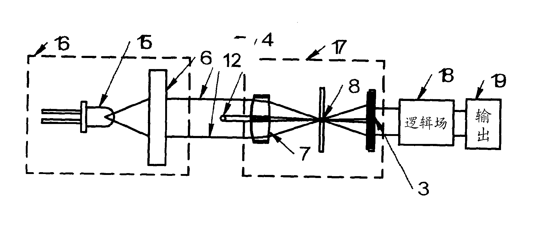
[0052] Figure 1 shows a diagram of the basic embodiment. Monochromatic point sources such as laser diodes 1 is placed on the collimating element 2 For example the focal point of a lens (a spherical lens or a doublet or a pair of cylindrical lenses). A collimated beam is produced at the output of the self-lens 12 . placed in the beam 12 fibers in 4 The image falls through the optical bandpass filter 11 on, and through an optical bandpass filter 11 Fall to CCD / CMOS sensor 3 superior. The image from the sensor is controlled by the programmable logic field 18 process and output 19 on record.

example 2

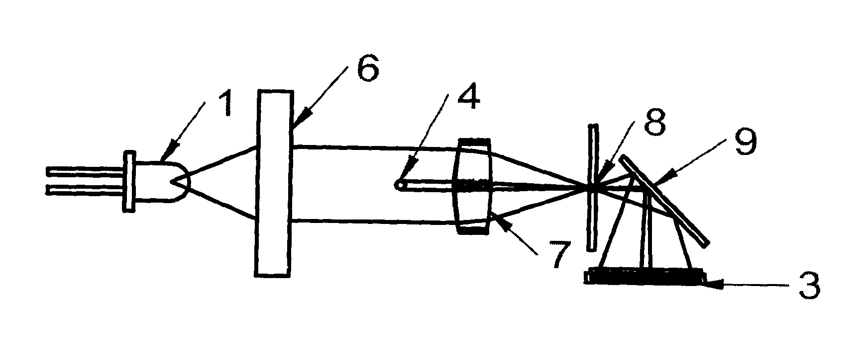
[0054] Figure 2 shows a modification of the former type of implementation, where a point source of light is used using a shutter 20 surface light source 15 (eg LED) replacement, which actually simulates a point light source as described in Example 1.

example 3

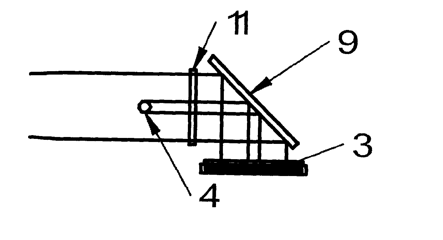
[0056] Figure 3 shows the mirror 9 is placed on the optical sensor 3 previous implementation. In this mirror with optical filter 11 and sensors 3 There is an angle of 45 degrees between them. This manner of embodiment may, for example, facilitate integration in compact devices.


PUM


Abstract

A method of continuous detection of the thickness and / or homogeneity of linear objects, particularly textile fibres, using a source of light as a part of the transmitter and an optical scanner to scan the light emitted by source as a part of the receiver. Combination of point or surface light source and collimating element as part of transmitter and combination of optical scanner and collimating element with pinhole as part of transmitter allows increased measuring area and accurate measurement of linear object thickness.

Description

technical field [0001] The invention relates to a method for the continuous detection of thread-like objects, in particular textile fibers (such as yarns, threads or strands) in the case of thread-like objects moving in a flow of light between a light emitter and a receiver Methods and equipment for thickness and / or uniformity. The invention can also be applied to threads and objects of other materials such as plastics and other polymers. The radiation receiver also has a CCD or CMOS radiation sensor or other types of image sensors composed of regularly distributed photosensitive elements, which determine the actual size of linear objects by evaluating the level of illumination of each element of the image sensor and according to the number of shaded elements. thickness to scan images of moving linear objects. [0002] The invention also relates to a device for applying the method described above, said device consisting of a radiation emitter and a receiver. The emitter con...

Claims


Application Information

Patent Timeline
IPC IPC(8): G01B11/10G01N21/89G01B11/06G01B11/08G01B11/24
CPCB65H63/065B65H2701/31D01H13/32G01B11/06G01B11/08G01B11/2433G01N21/8915
Inventor 彼得·珀纳约瑟夫·苏斯卡
Owner 彼得·珀纳
Learn More