Stray light testing method and system for optical system to be inspected
An optical system and detection method technology, applied in the field of optics, can solve problems such as difficult comparison, different experimental conditions and use conditions, unsatisfactory prediction of use effects, etc., to achieve the effect of avoiding uncertainty
- Summary
- Abstract
- Description
- Claims
- Application Information
AI Technical Summary
Problems solved by technology
Method used
Image

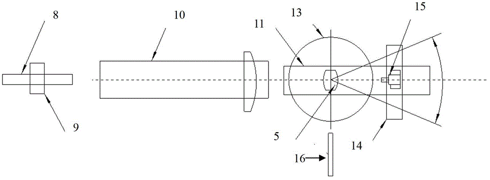
Examples
Embodiment Construction
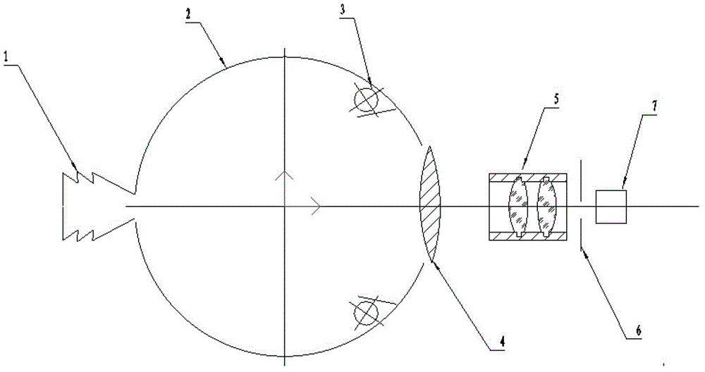
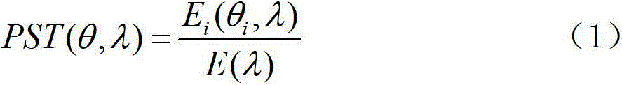
[0056] From the definition and expression of the point source transmittance, it can be seen that it is actually a detectable technical index, as long as the irradiance E i (θ, λ) and the irradiance E(λ) at the entrance pupil, then the point source transmittance PST of the system under test can be calculated according to formula (1). Therefore, the present invention provides a kind of stray light test system, the structural diagram of this system is as follows figure 2 shown.
[0057] The present invention firstly provides a stray light detection method of the optical system to be tested, the stray light detection method of the optical system to be tested comprises the following steps:
[0058] 1) Obtain the irradiance of the image plane of the optical system under test at different viewing angles;
[0059] 1.1) The laser beam is converted into a parallel beam and incident to the optical system to be tested;
[0060] 1.2) Measure the irradiance of the image plane of the opt...
PUM
 Abstract
Description
Claims
Application Information
 - R&D
- Intellectual Property
- Life Sciences
- Materials
- Tech Scout
- Unparalleled Data Quality
- Higher Quality Content
- 60% Fewer Hallucinations
Browse by: Latest US Patents, China's latest patents, Technical Efficacy Thesaurus, Application Domain, Technology Topic, Popular Technical Reports.
© 2025 PatSnap. All rights reserved.Legal|Privacy policy|Modern Slavery Act Transparency Statement|Sitemap|About US| Contact US: help@patsnap.com