
Strip-shaped grate concrete filled steel tube combined structure shear wall and preparation method thereof

A technology of steel tube concrete and composite structure, which is applied in the direction of walls, building components, building structures, etc., and can solve the problems of complex structure of double-layer steel plate shear wall, unreliable force of tensile structure, and lack of restoring force strength. , to achieve the effects of avoiding out-of-plane buckling damage, simple manufacturing and processing methods, and improved structural ductility

Inactive Publication Date: 2015-06-03
SOUTHEAST UNIV
View PDF5 Cites 0 Cited by
  • Summary
  • Abstract
  • Description
  • Claims
  • Application Information

AI Technical Summary

Problems solved by technology

[0004] The existing double-layer steel plate shear wall structure technology has more or less deficiencies and is not mature enough. Some double-layer steel plates adopt simple bolt tie connection measures, and the force of the tension structure is unreliable; The multi-story steel plate shear wall has a complex structure, and it cannot be poured into concrete to form a combined shear wall structure, which cannot bear vertical loads; some corrugated steel plate shear walls with pure steel structures do not have restoring strength after buckling, and their ductility is extremely high. Difference

Method used


Image

  • Strip-shaped grate concrete filled steel tube combined structure shear wall and preparation method thereof
  • Strip-shaped grate concrete filled steel tube combined structure shear wall and preparation method thereof
  • Strip-shaped grate concrete filled steel tube combined structure shear wall and preparation method thereof

Examples


Embodiment 1

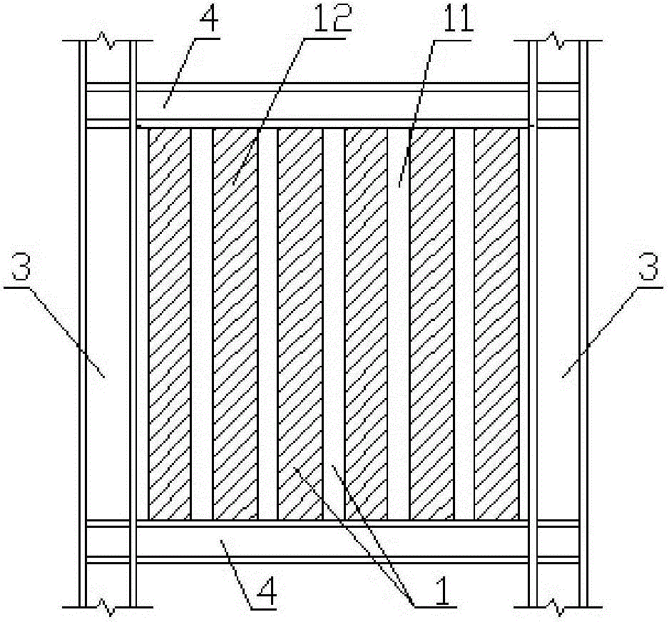
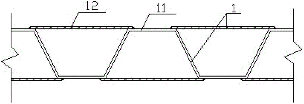
[0043] The shear wall of the composite structure of steel pipe concrete with elongated grid includes steel pipe wall plate 1 with elongated grid, reinforced concrete column 2 inside the pipe, edge steel column 3 and edge steel beam 4 . The elongated grid steel pipe wall panel 1 is composed of corrugated steel plate 11 and several steel strip cover plates 12 vertically welded and connected. , forming a long-strip steel structure hollow panel wall shape with multiple cavities, the strip-shaped grid steel pipe wall panel 1 contains two or more cavities, and the space of the strip-shaped grid steel pipe wall panel 1 Reinforced concrete columns 2 are arranged in the cavity, the left and right sides of the elongated grid steel pipe wall panel 1 are welded to the edge steel column 3, and the upper and lower sides of the elongated grid steel pipe wall panel 1 are welded to the edge steel beam 4;

[0044] In-pipe reinforced concrete column 2 includes in-pipe concrete 21, corrugated ste...

Embodiment 2

[0046] The preparation method of the above-mentioned elongated grid steel pipe concrete composite structure shear wall comprises the following steps:

[0047] Step 1: In the processing plant, tidy up the site, organize the construction materials, and carry out blanking of the corrugated steel plate 11 according to the design requirements. 11 and the inner surface of the steel strip cover plate 12 are welded firmly, and then, several steel strip cover plates 12 are completely covered with the notch of the corrugated steel plate 11, and the two are welded and connected firmly, and the vertical steel bar 24 in the pipe is inserted into the tie hoop The four corners of the rib-shaped enclosing frame form a strip-shaped grid steel pipe wall panel 1 with a welded steel skeleton;

[0048] Step 2: pouring self-compacting high-strength concrete into the cavity of the strip-shaped grid steel pipe wall panel 1 to form the concrete 21 in the pipe, curing the concrete, and waiting for the ...

Embodiment 3

[0051] A 100-story super high-rise steel structure building adopts a frame shear wall steel structure system. The frame columns are square concrete-filled steel tube columns, and the frame beams are made of H-shaped steel. The height of the bottom three floors is 4.5 meters, and the height of the rest is 3.6 meters. Because it is a super high-rise building, in order to resist wind and earthquake, multiple new strip-shaped grid steel pipe concrete composite structure shear walls are set up. One of the shear walls has a net length of 5.4 meters, and a long grid steel pipe wall panel composed of trapezoidal corrugated steel plates is selected, such as Figure 1 to Figure 5 The dimensions of the corrugated steel plate on the bottom fifteen floors are 900mm in wavelength, 300mm in wave height, 300mm in horizontal length of the straight plate section, 150mm in projected length of the inclined plate section, and 650mm in width of the steel strip cover plate; 800mm, the wave height is...


PUM


Abstract

The invention provides a strip-shaped grate concrete-filled steel tube combined structure shear wall, which comprises a strip-shaped grate steel tube wall plate and reinforced concrete columns inside tubes. A corrugated sheet steel and a plurality of steel sheet strip cover plates are vertically welded, so that the strip-shaped grate steel tube wall plate is formed; a vertical groove of the corrugated sheet steel is covered by the steel sheet strip cover plates, and then a plurality of cavities are formed, high-strength concrete is poured in the cavities, a strip-shaped grate concrete-filled steel tube combined structure shear wall plate is formed, and the shear wall plate is welded with margin steel columns and margin steel beams. The grate steel tube wall plate and the high strength reinforced concrete columns inside tubes are combined for usage, advantages are complementary, teamwork is achieved, lateral deformation of concrete inside the tubes is restricted by the grate steel tubes, hooped reinforcements of the reinforced concrete columns inside the tubes and the grate steel tubes are welded and tied, so that the bending resistance of the grate steel tube wall plate can be improved. The strip-shaped grate concrete-filled steel tube combined structure shear wall has the advantages that the structural rigidity is high, the construction is quick, the bending resistance is high, the yield load is high, the ductility is good, the energy consumption performance is good, the construction cost is low, and the like. The shear wall can be applied to an ultrahigh steel structure building.

Description

technical field [0001] The invention belongs to the field of building structure engineering, and relates to a composite structure shear wall, in particular to a long grid steel tube concrete composite structure shear wall. Background technique [0002] High-rise steel structure buildings represent the development direction of future building structures. It has comprehensive advantages such as high strength, light weight, low foundation costs, high degree of industrialization, short construction period, good seismic performance, fast investment recovery, and less environmental pollution. With the increase of my country's steel output and the development of real estate construction, high-rise steel structure buildings have been more and more used. my country is an earthquake-prone country. In order to ensure the seismic safety of high-rise steel structure buildings, it is necessary to set up a lateral force-resistant shear wall structure system to resist strong earthquakes. ...

Claims


Application Information

Patent Timeline
Patent Type & Authority Patents(China)
IPC IPC(8): E04B2/56E04B2/58E04B2/64E04G21/00
Inventor 徐文平郭训黄明周广如王志明孔维平陈有春卢建峰王勇
Owner SOUTHEAST UNIV
Learn More