
Delay power supply

A delayed power supply and power supply technology, applied in the power supply field, can solve problems such as CMOS chip latch, hardware damage, and damaged chips, and achieve the effects of convenient processing and production, preventing failures, and delaying power supply

Inactive Publication Date: 2013-06-05
XIAN JINHE OPTICAL TECH
View PDF0 Cites 2 Cited by
  • Summary
  • Abstract
  • Description
  • Claims
  • Application Information

AI Technical Summary

Problems solved by technology

[0002] The power supply is an indispensable part of electrical appliances. When the power supply is turned on, there will be a spike current due to various reasons. Although the time is very short, the surge current is fatal to many sophisticated electronic equipment and components, often causing Equipment failure or instability
In addition, restarting the electronic device immediately after shutdown will also have an impact. Since some components in the electronic device that have just been turned off, such as capacitors, inductors and other energy storage components, still have a certain amount of electric energy, restarting immediately after shutdown may cause some problems. If the inductance induces a high voltage to damage other components, it may also cause the latch-up phenomenon of the CMOS chip, which will seriously damage the chip or even the device.
On the other hand, due to the improvement of the intelligence of the current electronic equipment, the switch control of the power supply can also be realized by software, and some virus software takes advantage of this point. When the virus software controls the electronic equipment, it repeatedly shuts down and restarts the equipment , which is very harmful to hardware; with the expansion of the concept of information warfare, terrorist organizations or hostile forces can also use this feature to implant virus software into key equipment, or tens of millions of microcomputers. Once the conspiracy succeeds, other The loss may be as much as a war

Method used


Image

  • Delay power supply

Examples


Embodiment Construction

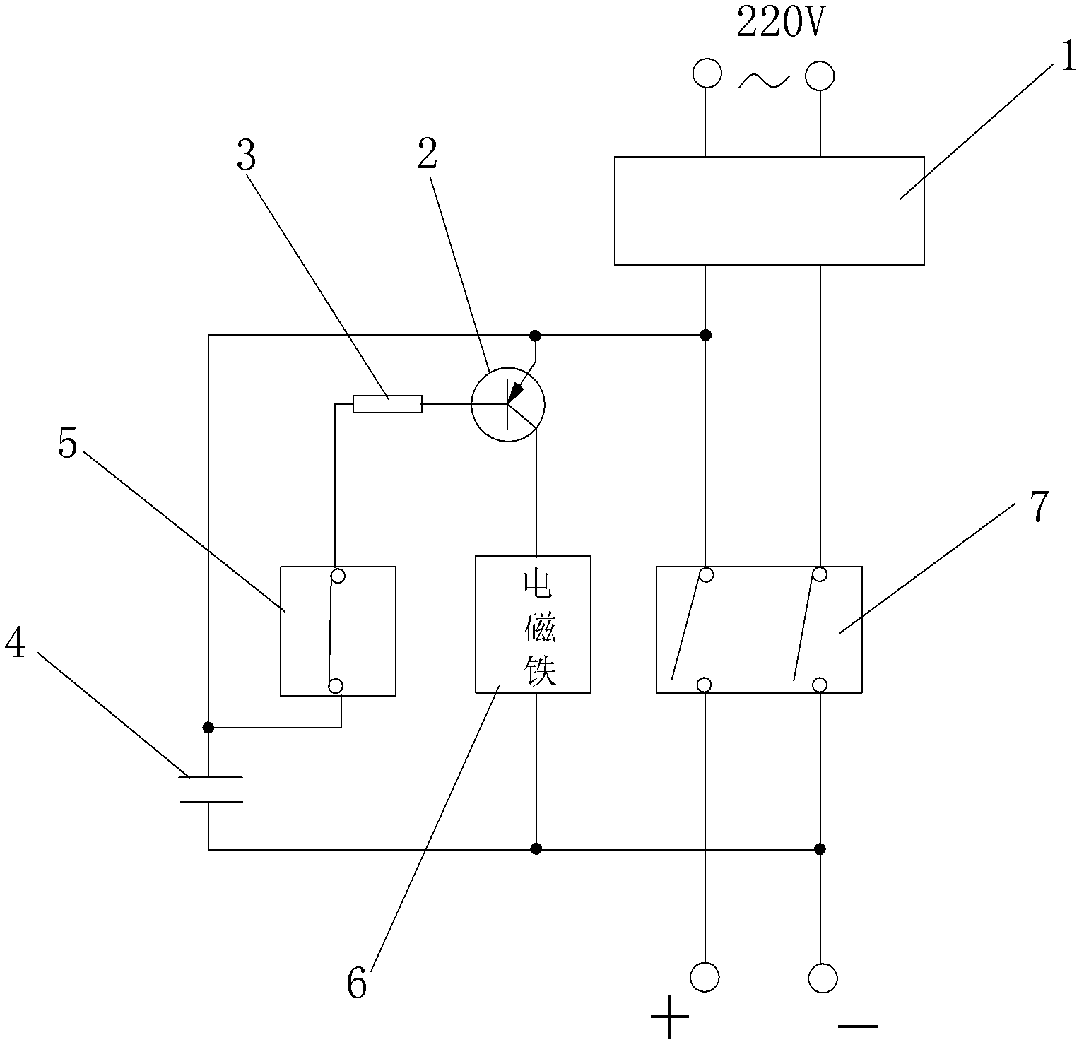
[0016] Such as figure 1 The shown delay power supply includes a rectifier module 1 that converts mains electricity into mortgaged direct current, in particular: includes a PNP transistor 2, the emitter electrode of which is connected to the positive pole of direct current, and the collector of the PNP transistor 2 is connected to an electromagnet 6 connection, the resistor 3 is connected to the base of the PNP transistor 2, the other end of the resistor 3 is connected to the normally closed relay 5, the normally closed relay 5 is connected between the capacitor 4 and the positive pole of the direct current, and the other end of the capacitor 4 is connected to the negative pole of the direct current, The other end of the electromagnet 6 is also connected to the negative pole of the direct current, and a normally open two-way relay 7 is arranged on the lead of the direct current, and the electromagnet 6 controls the normally closed relay 5 and the normally open two-way relay 7 at...


PUM


Abstract

The invention discloses a delay power supply. The delay power supply comprises a rectifying module for converting mains supply into low-voltage direct current and a PNP triode, wherein the emitter electrode of the PNP triode is connected with the anode of the direct current, the collector of the PNP triode is connected with an electromagnet, and a resistor is connected with the base of the PNP triode; the other end of the resistor is connected with a normally-closed relay; the normally-closed relay is connected between a capacitor and the anode of the direct current; the other end of the capacitor is connected with the cathode of the direct current; the other end of the electromagnet is connected with the cathode of the direct current; a normally-open two-way relay is arranged on a lead of the direct current; and the electromagnet simultaneously controls the normally-closed relay and the normally-open two-way relay. The delay power supply can effectively prevent the impact current and prevent the influence brought by repeatedly turning on and off electronic equipment, has the characteristics of low cost, simplicity and practicability, and has popularization value.

Description

technical field [0001] The invention relates to a power supply, in particular to a delayed power supply. Background technique [0002] The power supply is an indispensable part of electrical appliances. When the power supply is turned on, there will be a spike current due to various reasons. Although the time is very short, the surge current is fatal to many sophisticated electronic equipment and components, often causing Equipment failure or instability. In addition, restarting the electronic device immediately after shutdown will also have an impact. Since some components in the electronic device that have just been turned off, such as capacitors, inductors and other energy storage components, still have a certain amount of electric energy, restarting immediately after shutdown may cause some problems. If the inductance induces a high voltage to damage other components, it may also cause the latch-up phenomenon of the CMOS chip, and seriously damage the chip or even the d...

Claims


Application Information

Patent Timeline
IPC IPC(8): H02M7/02H03K17/28
Inventor 杜兵
Owner XIAN JINHE OPTICAL TECH
Learn More