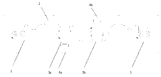
Lithium ion battery diaphragm, preparation method of the lithium ion battery diaphragm, and lithium ion battery containing the lithium ion battery diaphragm
A lithium ion battery and separator technology, applied in the field of lithium ion battery separator and its preparation, can solve the problems of increasing positive and negative short circuits and thermal runaway, and achieve the effects of reducing the risk of short circuit and high lithium ion conduction speed
- Summary
- Abstract
- Description
- Claims
- Application Information
AI Technical Summary
Problems solved by technology
Method used
Image
Examples
Embodiment 1
[0047] (1) Substrate preparation:
[0048] High-density polyethylene (Mw=250000, Mw / Mn=12) was made into a raw film through a twin-screw extruder at a temperature of 220°C and a draw ratio of 5. The raw film was preheated for 2 hours at a temperature of 120°C. Then, the film with a width of 400 mm was stretched longitudinally at a stretching ratio of 25, a stretching rate of 37 m / min, and a temperature of 120° C. A separator substrate with a porosity of 60% and a thickness of 16 μm was obtained.
[0049] (2) Surface modification coating
[0050] Fix the substrate with a width of 400mm and a length of 1000m and a thickness of 16μm in the unwinding device and winding device of the winding continuous coating equipment, the size is 400*80*6 square Li 3 PO 4 The targets were respectively installed in physical vapor deposition device a and physical vapor deposition device b, the coating chamber was closed, and the vacuum was evacuated to 5×10 -2 Pa; Then, adjust the ventilation...
Embodiment 2
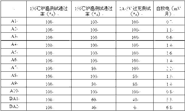
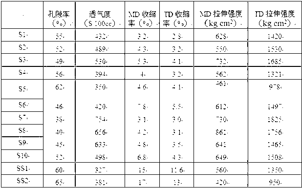
[0054] The same method as in Example 1 was used to prepare the separator substrate, the surface modification coating and the battery. The difference is: the target is Li 2 S, Li 2 The thickness of the S coating is 100nm; then the Li 2 S is replaced by a square PVC target with a size of 400*80*2, and then a layer of organic polymer layer is sputtered on the surface, the sputtering power is 1500W, and the line speed is 60m / h, and the diaphragm with a 400nm thick PVC layer deposited on the surface is obtained. , denoted as S2; the manufactured battery is denoted as A2.
Embodiment 3
[0056] The same method as in Example 1 was used to prepare the separator base material, the surface modification coating and the battery. The difference was that the target size used first was a square PTFE target with a size of 400*80*2, the sputtering power was 1500W, and the linear speed was 40m / h, to obtain a diaphragm with a 2000nm thick PTFE layer deposited on the surface, and then replace the PTFE target with a square Li with a size of 400*80*6 2 SiO 3 The target is installed in the coating equipment, the coating chamber is closed, and the vacuum is evacuated to 5×10 -2 Pa; then, adjust the vent valve to feed argon and oxygen, wherein the argon flow is 20sccm, the oxygen flow is 120sccm, the sputtering power is adjusted to 1000W, and the coating is performed at a linear speed of 80m / h to obtain a surface deposition of 500nm thick Li 2 SiO 3 The separator of the first layer is denoted as S3; the fabricated battery is denoted as A3.
PUM
| Property | Measurement | Unit |
|---|---|---|
| Thickness | aaaaa | aaaaa |
| Thickness | aaaaa | aaaaa |
Abstract
Description
Claims
Application Information
 - R&D
- Intellectual Property
- Life Sciences
- Materials
- Tech Scout
- Unparalleled Data Quality
- Higher Quality Content
- 60% Fewer Hallucinations
Browse by: Latest US Patents, China's latest patents, Technical Efficacy Thesaurus, Application Domain, Technology Topic, Popular Technical Reports.
© 2025 PatSnap. All rights reserved.Legal|Privacy policy|Modern Slavery Act Transparency Statement|Sitemap|About US| Contact US: help@patsnap.com


