
Electro-hydraulic control system of disc type braking device of mine belt conveyor

An electro-hydraulic control system, belt conveyor technology, applied in conveyor control devices, conveyors, conveyor objects, etc., can solve problems such as failure to brake, affect normal work, and block oil circuits, and achieve constant reduction. Speed ​​braking, high reliability effect

Inactive Publication Date: 2015-05-20
TAIYUAN UNIV OF TECH
View PDF6 Cites 0 Cited by
  • Summary
  • Abstract
  • Description
  • Claims
  • Application Information

AI Technical Summary

Problems solved by technology

[0003] However, there are also some shortcomings in the use of disc brakes in belt conveyors in coal mines: first, several pairs of brake heads return oil uniformly. If the belt conveyor starts and the oil circuit is blocked, it will cause braking The head cannot be opened normally, which affects normal work; if the oil circuit is blocked during braking, it will not be able to return the oil, cannot brake, and an accident will occur, which will cause serious loss of life and property; secondly, in the belt conveyor During normal operation, the motor and oil pump are always in working condition to provide pressure for the brake head, and the long-time working system seriously affects the service life of the motor and pump
Before the system is used, the system must first charge the accumulator; the gear pump always works with the roller during the working process, and the service life of the gear pump is greatly affected; a unified circuit is used to return oil, and when the circuit is blocked, the impact normal working of the system

Method used


Image

  • Electro-hydraulic control system of disc type braking device of mine belt conveyor

Examples


specific Embodiment approach

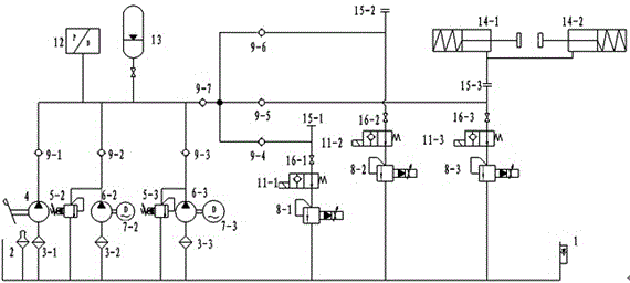
[0034] as attached figure 1As mentioned above, when the belt conveyor is working, a start signal is sent out, and after PLC processing, the electromagnetic reversing valve 11 is controlled to be energized to the left position, and at the same time the flameproof motor Ⅱ7-2 is started, driving the plunger pump Ⅱ6-2 to work from the oil tank Oil suction, the oil passes through the check valve Ⅱ9-2 to flush the accumulator 13, the oil flows through the check valve Ⅶ9-7 and is divided into multiple paths, any oil path passes through the check valve, and the oil is divided into two paths , one way enters the hydraulic cylinder of the brake head 14, the disc spring is compressed to release the brake head, and the other way flows to the electromagnetic reversing valve 11; after the pressure transmitter 12 detects that the system pressure reaches the set value, it returns to the PLC signal to control the explosion-proof motor Ⅱ7-2 to lose power, stop working, return a start signal to ...


PUM


Abstract

An electro-hydraulic control system of a disc type braking device of a mine belt conveyor comprises a power part and an execution part, wherein the power part is communicated with the execution part through a one-way valve and achieves electro-hydraulic control on the disc type braking device through a programmable logic controller (PLC) program. The power part is divided into three paths, wherein one path is a hand pump, each of another two sets consists of an explosive-proof motor and a plunger pump, and each path independently returns oil through an electro-magnetic proportional over-flow valve and a magnetic exchange valve. The execution part is divided into at least two execution return circuits through one-way valves, wherein each execution return circuit is divided into two paths through a one-way valve, one path of each execution return circuit is connected into a hydraulic cylinder of a brake head, and the other path of each execution return circuit is communicated with an oil tank through a throttle valve, a magnetic exchange valve and an electro-magnetic proportional over-flow valve. The electro-hydraulic control system is composed of the three paths of power sources, automatic switching control is achieved, reliability and stability of the system are further improved, the system structure is instantaneously controlled, energy consumption is reduced, and the service life of the device is prolonged.

Description

technical field [0001] The invention relates to a disc brake control device for a belt conveyor, in particular to a multi-circuit instantaneous electro-hydraulic control system for the disc brake device of a belt conveyor in a coal mine. Background technique [0002] The belt conveyor is the only continuous transportation device with the largest coal conveying capacity, the highest efficiency, and the most economical in the existing coal mine. The disc brake device is a key component of the existing belt conveyor to realize the safety and automatic control. Its system Whether the function is perfect, the performance is good or bad, and the length of the braking input time directly affects the safe and reliable operation of the belt conveyor. [0003] However, there are also some shortcomings in the use of disc brakes in belt conveyors in coal mines: first, several pairs of brake heads return oil uniformly. If the belt conveyor starts and the oil circuit is blocked, it wi...

Claims


Application Information

Patent Timeline
Patent Type & Authority Patents(China)
IPC IPC(8): B65G23/26B65G43/00
Inventor 李军霞宫学东张延军庞晓旭寇子明杜建伟霍国涛俞晶
Owner TAIYUAN UNIV OF TECH
Learn More