Solar Automatic soaking and gathering-heat pipe, slot-typed assembly, thermal power generating system and craft

一种太阳能、聚热管的技术,应用在太阳能光热发电领域,能够解决真空集热管上下温差大、毁坏真空集热管爆管事故、导热性导热性差别很大等问题,达到避免爆管事故的效果

Active Publication Date: 2013-05-22
ZHONGYING CHANGJIANG INTERNATIONAL NEW ENERGY INVESTMENT CO LTD
View PDF5 Cites 11 Cited by
  • Summary
  • Abstract
  • Description
  • Claims
  • Application Information

AI Technical Summary

Problems solved by technology

And if the absorption tube 1b3 is filled with water, when the water temperature rises above 100°C, the water will be easily vaporized to produce water vapor, and the vacuum heat collection tube of the trough system is very long and placed horizontally. On the surface, it will form a two-phase flow state in which the upper half is steam and the lower half is water in the absorption tube 1b3. The thermal conductivity of steam is very different from that of liquid water. The temperature difference is very large, and a large internal stress is generated due to thermal expansion and cold contraction, and a tube explosion accident that destroys the vacuum heat collecting tube occurs

Method used


Image

  • Solar Automatic soaking and gathering-heat pipe, slot-typed assembly, thermal power generating system and craft
  • Solar Automatic soaking and gathering-heat pipe, slot-typed assembly, thermal power generating system and craft
  • Solar Automatic soaking and gathering-heat pipe, slot-typed assembly, thermal power generating system and craft

Examples


Embodiment Construction

[0035] The present invention will be described in detail below in conjunction with the accompanying drawings and the best mode of implementation.

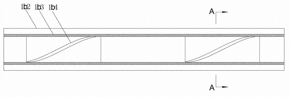
[0036] figure 2 It is a structural schematic diagram of the first embodiment of the solar automatic heat-spreading heat-gathering tube of the present invention. Among them, 1b2 is the glass tube of the outer layer of the solar automatic heat soaking tube, 1b3 is the absorption tube coated with a heat absorbing layer on the inner layer of the solar automatic heat soaking tube (1b3 is usually made of stainless steel, beryllium alloy (such as beryllium bronze) and other high temperature resistant Metal material, the space between 1b2 and 1b3 is a vacuum), 1b4 is the isolation plate set in the inner cavity of the absorption tube 1b3, 1b4 is made of the same material as 1b3 or a material with similar thermal performance. A-A indicates the position and view direction of the cross-section of the forced-heating trough module (that is, cut...


PUM


Abstract

The invention relates to a solar automatic soaking and gathering-heat pipe, a slot-typed assembly, a thermal power generating system and a craft. The solar automatic soaking and gathering-heat pipe comprises a glass tube and an absorption tube which is installed inside the glass tube and is coated with an endothermic layer. Vacuum is arranged between the glass tube and the absorption tube. The solar automatic soaking and gathering-heat pipe is characterized in that segregation board which is used for enabling fluid to turn flow up and down alternatively in the absorption tube and is installed inside the inner chamber of the absorption tube. The segregation board is in a heliciform and is fixed in the absorption tube enabling the solar automatic soaking and gathering-heat pipe to be filled with water to heat directly without the worry of booster. Meanwhile, the electrical power generating system and the craft through photo-thermal supplementary electricity generation enables the photo-thermal supplementary power station to be unaffected by the weather so that the electricity can be generated steadily at night or when the sunlight is inadequate. Energy conservation and environment protection can be achieved.

Description

technical field [0001] The invention relates to a thermal power generation process, device / system and process for directly passing water through solar trough heat collecting tubes, and belongs to the technical field of solar thermal power generation. Background technique [0002] Solar energy has wide distribution, unlimited reserves, clean collection and utilization, CO 2 The advantages of zero emissions have attracted widespread attention. For a long time, in the field of solar thermal power generation technology, there have been three power generation modes, namely tower type, dish type, and trough type (including parabolic mirror trough type and Fresnel mirror trough type). [0003] In prior art trough solar thermal power generation systems, steam turbines are used to finally drive the motor to generate electricity, and the working medium is water vapor. However, in the current existing technology, in the vacuum heat collecting tube of the trough solar thermal power ge...

Claims


Application Information

Patent Timeline
Patent Type & Authority Applications(China)
IPC IPC(8): F24J2/46F03G6/06F24S10/40F24S10/70F24S10/75F24S20/20F24S23/71F24S23/74F24S90/00
CPCF22B33/00F22B1/006F24J2/00Y02E10/46Y02E10/44F24S10/45F24S20/20F24S23/74F24S2080/05F03G6/065F01K13/00F24S90/00F24S10/40F24S20/61F24S20/25F24S10/754F24S2010/751Y02E10/40F03G6/061
Inventor 陈义龙杨清萍张岩丰
Owner ZHONGYING CHANGJIANG INTERNATIONAL NEW ENERGY INVESTMENT CO LTD
Why Eureka
Try Eureka