
Control device of lifting mechanism of industrial vehicle and control method

A technology for industrial vehicles and lifting mechanisms, used in lifting devices, fluid pressure actuation devices, mechanical equipment, etc., can solve the problem of affecting the performance and service life of motors and hydraulic pumps, and is not suitable for large-scale promotion and application. problems such as low efficiency, to achieve the effect of improving stability and safety, reducing impact and energy consumption, and reducing time

Active Publication Date: 2013-05-22
NOBLEELEVATOR INTELLIGENT EQUIP CO LTD
View PDF7 Cites 16 Cited by
  • Summary
  • Abstract
  • Description
  • Claims
  • Application Information

AI Technical Summary

Problems solved by technology

[0002] Industrial vehicles such as forklifts and trucks are all provided with a vehicle lifting device that lifts up the goods. For example, the Chinese utility model patent with the publication number CN201560102U and the publication date on August 25, 2010 discloses a fork lifting device and Electric forklifts use reducers, lead screws, motors, and chains to achieve lifting actions. Such a lifting device is controlled by a motor driven screw. Its structure is very complicated, its cost is high, and its competitiveness is low. It is not suitable for large-scale Popularization and application, so people began to use hydraulic lifting devices, using hydraulic control devices to control the lifting device or lifting mechanism to complete the lifting action, the control devices include hydraulic pumps, check valves, overflow valves, etc. Strong performance, but also has disadvantages: limited by the cost, it uses quantitative pumps, generally gear pumps, and overflow valves are used to control the working pressure of the system. Therefore, each lifting of the lifting device is Rigid, that is to say, the hydraulic pump and the motor are working at full load from beginning to end. The heavier the lifted load, the higher the output power requirement of the motor. In this way, the motor will often start under full load. , over time, it will not only affect the performance and service life of the motor and hydraulic pump, but also cause the entire control device to have low working efficiency and poor stability

Method used


Image

  • Control device of lifting mechanism of industrial vehicle and control method

Examples


Embodiment Construction

[0042] The following descriptions are only preferred embodiments of the present invention, and do not limit the scope of the present invention.

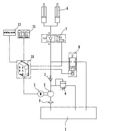
[0043] Examples, see attached figure 1 A control device for an industrial vehicle lifting mechanism, including a fuel tank 1, a quantitative hydraulic pump 2, a motor 3 that drives the quantitative hydraulic pump 2 to rotate, an overflow valve 4 connected to the outlet of the quantitative hydraulic pump 2, and a one-way valve 5 , a hydraulic cylinder 6, an electromagnetic reversing valve 7 arranged between the one-way valve 5 and the hydraulic cylinder 6, and an electromagnetic proportional valve connected to the outlet of the hydraulic pump 2 and connected in parallel with the electromagnetic reversing valve 7 8. A programmable controller 10 for controlling the opening and closing of the motor 3, controlling the opening and closing of the electromagnetic reversing valve 7, and controlling the opening of the electromagnetic proportiona...


PUM


Abstract

The invention discloses a control device of a lifting mechanism of an industrial vehicle and a control method. The control device comprises an oil tank, a quantitative hydraulic pump, a motor for driving the quantitative hydraulic pump to rotate, an overflow valve communicated with an exit of the quantitative hydraulic pump, a one-way valve, a hydraulic oil cylinder, a magnetic exchange valve arranged between the one-way valve and the hydraulic oil cylinder, an electromagnetic proportional valve communicated with the exit of the hydraulic pump and in parallel connection with the magnetic exchange valve, a programmable logic controller for controlling on-off of the motor, opening and closing of the magnetic exchange valve and the aperture of an opening of the magnetic exchange valve, a proportional lifting button connected with the programmable logic controller and provided with an ascending button and a descending button, and a weighing system. The control device of the lifting mechanism of the industrial vehicle and the control method are capable of improving service life of the quantitative hydraulic pump and the motor and reducing energy consumption and impact, stable in operation, good in safety, precision in positioning and high in efficiency of the whole system.

Description

technical field [0001] The invention relates to the technical field of industrial vehicles, and more specifically relates to a control device and a control method for an industrial vehicle lifting mechanism. Background technique [0002] Industrial vehicles such as forklifts and trucks are all provided with a vehicle lifting device that lifts up the goods. For example, the Chinese utility model patent with the publication number CN201560102U and the publication date on August 25, 2010 discloses a fork lifting device and Electric forklifts use reducers, lead screws, motors, and chains to achieve lifting actions. Such a lifting device is controlled by a motor driven screw. Its structure is very complicated, its cost is high, and its competitiveness is low. It is not suitable for large-scale Popularization and application, so people began to use hydraulic lifting devices, using hydraulic control devices to control the lifting device or lifting mechanism to complete the lifting ...

Claims


Application Information

Patent Timeline
IPC IPC(8): B66F9/22F15B21/02
Inventor 周学军周敏龙施林强
Owner NOBLEELEVATOR INTELLIGENT EQUIP CO LTD
Learn More