
Pressure seam welding method and device

A technology of thinning seam welding and holding device, which is applied in the direction of roller electrode welding, welding equipment, welding power supply, etc., and can solve the problems of large damage to the electrode wheel, inability to obtain welding results, welding spatter current density, etc.

Active Publication Date: 2015-12-02
PRIMETALS TECHNOLOGIES JAPAN LTD
View PDF9 Cites 0 Cited by
  • Summary
  • Abstract
  • Description
  • Claims
  • Application Information

AI Technical Summary

Problems solved by technology

[0004] In Patent Document 1, the following problem is proposed as a problem in the case of joining thick metal plates: as in Patent Document 1, Figure 13 As shown, the sheet metal (the material to be welded) must be bent quite extreme, which exerts considerable force on the clamping device, thus causing the clamping device to deform or even break
[0005] In Patent Document 2, as a problem in the case of joining high-strength steel plates, the following problems are raised: Referring to FIG. 20) is in contact with the electrode wheel, so the damage caused to the electrode wheel is relatively large, and because the welding current is concentrated at the corner of the lower metal plate (21 of Figure 8 of Patent Document 2), welding spatter (corner part The phenomenon that the current density is excessive, so that the melting is scattered, and the sputtering remains on the metal plate), and good welding results cannot be obtained.
Similarly, in the case of joining thick metal plates, the current needs to be increased due to the increase in the volume of the joint, and the pressing force of the electrode wheel must be increased because the rigidity of the metal plates becomes higher. The same principle will produce the same problem in the situation

Method used


Image

  • Pressure seam welding method and device
  • Pressure seam welding method and device
  • Pressure seam welding method and device

Examples


Embodiment Construction

[0103] Next, embodiments of the present invention will be described with reference to the drawings.

[0104] figure 1 It is a figure which shows the outline of the structure of the mash seam welding apparatus of the metal plate which concerns on one Embodiment of this invention.

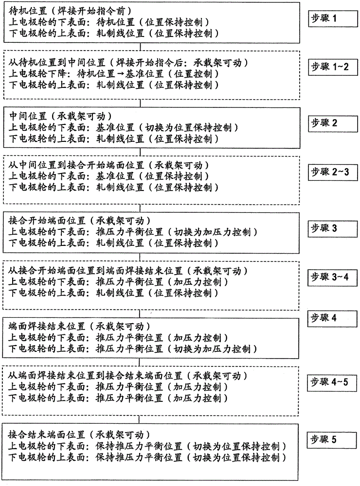
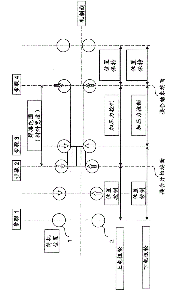
[0105] figure 1 Among them, the mash seam welding device of this embodiment includes: a pair of upper and lower electrode wheels 1, 2; a pair of upper and lower pressure rollers 3, 4; first and second holding devices 7, 8; a carrier frame 9; upper and lower electrodes Wheel pressing devices 10a, 10b; and upper and lower pressure roller pressing devices 11a, 11b. The upper and lower electrode wheel pressing devices 10a, 10b and the upper and lower pressure roller pressing devices 11a, 11b are, for example, hydraulic or pneumatic cylinder devices. The upper electrode wheel 1 and the upper pressing roller 3 are respectively supported on the upper horizontal frame 9a of the carrier frame 9 via the u...


PUM

PropertyMeasurementUnit
thicknessaaaaaaaaaa
thicknessaaaaaaaaaa
thicknessaaaaaaaaaa

Abstract

In mash seam welding for performing to weld metal plates with thicknesses of 2 mm or more, it is possible to stabilize the strength of a joint portion, reduce uneven parts of the joint portion, ensure high strength and reliability of the joint portion, and join metal plates with thicknesses of 4.5 mm or more. Two metal plates (5, 6) are clamped with first and second clamping devices (7, 8), and the two metal plates (5, 6) are placed to overlap each other at their end portions, and then overlapping portions (L) of the two metal plates 5, 6) are pressed with a pair of upper and lower electrode wheels (1, 2) while welding currents flow to continuously weld the overlapping portions (L) and join the two metal plates. The pessing forces applied to the upper and lower electrode wheels (1, 2) are controlled so that upper and lower welding forces acting upon the overlapping portions are equal to each other during the time when the overlapping portions are continuously welded while the welding currents flow.

Description

technical field [0001] The present invention relates to a mash seam welding method and device for joining two thick metal plates. Background technique [0002] Pressure seam welding is a welding method that overlaps the ends of two metal plates, pressurizes the overlapped part with a pair of electrode wheels, turns on the welding current, and performs welding continuously. The joint part heated to a high temperature state and softened is rolled, thereby reducing the thickness of the joint part. [0003] As the prior art of a mash seam welding apparatus for joining thick metal plates, for example, the techniques described in Patent Document 1 and Patent Document 2 are known. [0004] In Patent Document 1, the following problem is proposed as a problem in the case of joining thick metal plates: as in Patent Document 1, Figure 13 As shown, the sheet metal (the material to be welded) must be bent quite extreme, which exerts considerable force on the clamping device, thus causi...

Claims


Application Information

Patent Timeline
Patent Type & Authority Patents(China)
IPC IPC(8): B23K11/06B23K11/24B23K11/30
CPCB23K11/36B23K11/061B23K11/255B23K2201/18B23K2101/18B23K11/06B23K11/24B23K11/30
Inventor 加贺慎一小野濑满富永宪明斋藤武彦芳村泰嗣田方浩智佐藤惠一
Owner PRIMETALS TECHNOLOGIES JAPAN LTD
Learn More