Electric vehicle battery pack

A technology for electric vehicles and battery packs, which is applied to battery pack components, secondary batteries, vehicle components, etc. It can solve the problems of being sucked into the inside of the battery box and reducing ride comfort, and achieves the goal of reducing the number of parts and assembly man-hours Effect

Inactive Publication Date: 2013-05-15
HONDA MOTOR CO LTD
View PDF4 Cites 3 Cited by
  • Summary
  • Abstract
  • Description
  • Claims
  • Application Information

AI Technical Summary

Problems solved by technology

[0006] However, in the structure described in the above-mentioned Patent Document 1, the battery box is arranged in the vehicle interior, and when the battery box is arranged outside the vehicle and the air outside the vehicle is used as cooling air to cool the battery, not only the battery contained in the cooling air Dust or water may be sucked into the battery box from the air intake duct, and the noise and vibration generated by the cooling fan may be transmitted to the cabin, reducing the ride quality.

Method used


Image

  • Electric vehicle battery pack
  • Electric vehicle battery pack
  • Electric vehicle battery pack

Examples


Embodiment Construction

[0041] Below, based on Figure 1 to Figure 11 , the embodiment of the present invention will be described.

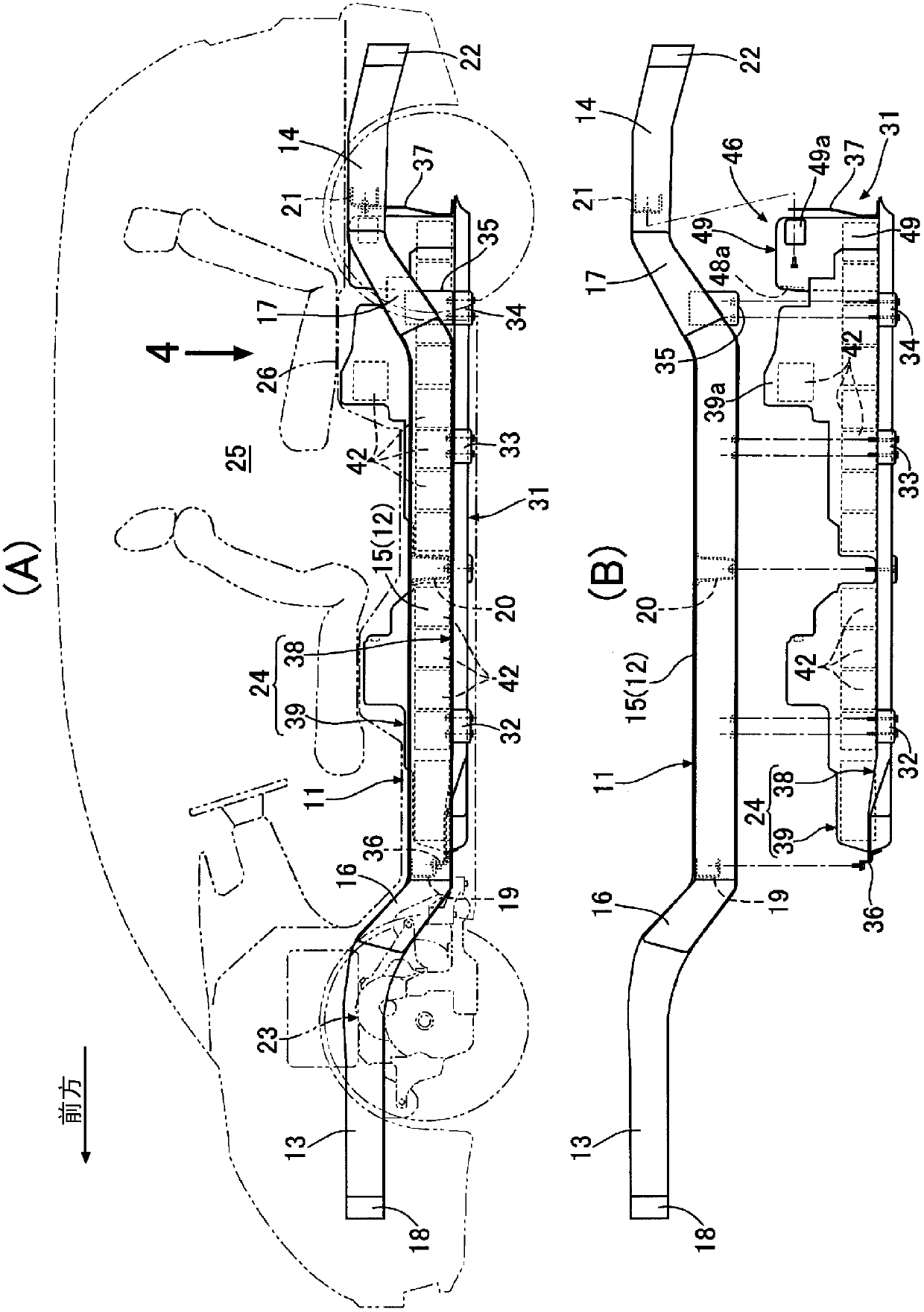
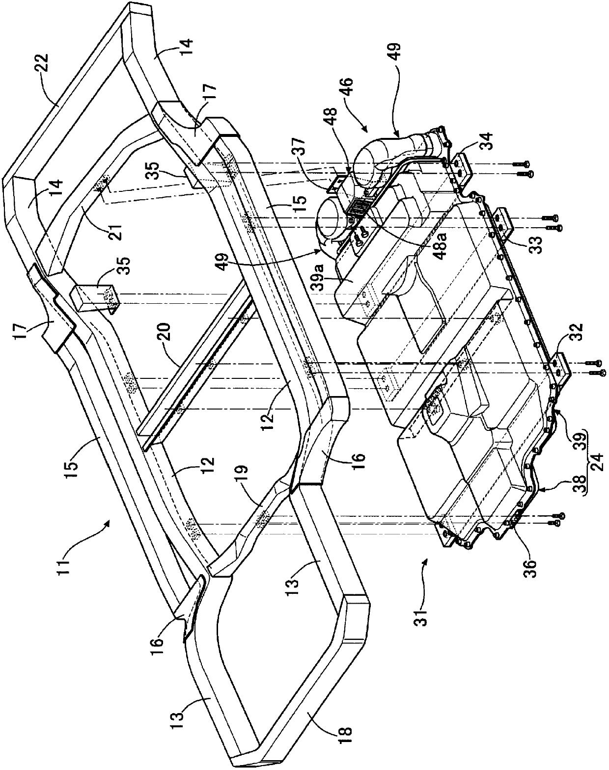
[0042] Such as figure 1 and figure 2 As shown, the frame 11 of the electric vehicle includes: a pair of left and right underframes 12, 12 extending in the front-rear direction of the vehicle body; Side frames 13, 13; a pair of left and right rear side frames 14, 14 extending rearward while being bent upward from the rear ends of the bottom frames 12, 12; Pair of side beams 15,15; a pair of left and right outriggers 16,16 connecting the front ends of side beams 15,15 with the front ends of bottom frames 12,12; connecting the rear ends of side beams 15,15 with bottom frames A pair of left and right rear outriggers 17,17 connected to the rear ends of 12,12; a front bumper 18 between the front ends of a pair of left and right front side frames 13,13 connected along the vehicle width direction; The front beam 19 connecting the front ends of the pair of left and right un...


PUM


Abstract

An electric vehicle battery pack includes a battery case (24), a cooling air intake member, a cooling air exhaust member, and a first cooling fan. The cooling air is to be drawn through the cooling air intake member (48) into a cooling passage. The cooling air intake member is disposed between the battery case and a passenger compartment. The cooling air is to be exhausted through the first cooling air exhaust member (49) from the cooling passage. The first cooling air exhaust member includes a first cooling air exhaust passage through which the cooling air from the cooling passage is to flow. The first cooling air exhaust member is disposed between the battery case and the passenger compartment. At least a part of the first cooling air exhaust passage is disposed between the first cooling fan and the passenger compartment.

Description

technical field [0001] The present invention relates to a battery pack for an electric vehicle, comprising: a battery box that accommodates a plurality of batteries and is arranged below a vehicle compartment; and a cooling air intake that sucks cooling air into a cooling passage formed inside the battery box. means; a cooling air discharge member for discharging cooling air from the cooling passage. Background technique [0002] The following structure is known from the following patent document 1: an air intake duct, a battery box, a first exhaust duct, a ventilation fan, and a second exhaust duct are connected in series, and the air sucked from the air intake duct by driving the ventilation fan is known. The air in the vehicle compartment is supplied to the battery box to cool the battery, and the exhaust gas discharged from the battery box is discharged through the first exhaust duct, the ventilation fan, and the second exhaust duct. [0003] prior art literature [00...

Claims


Application Information

Patent Timeline
Patent Type & Authority Applications(China)
IPC IPC(8): H01M10/50B60K1/04H01M2/10H01M10/60H01M10/613H01M10/625H01M10/6563H01M10/6566
CPCY02E60/12H01M10/50H01M10/5004H01M10/5016H01M10/5067H01M10/613H01M10/625H01M10/6563Y02E60/10
Inventor 片山吾一山本康一伊藤康介
Owner HONDA MOTOR CO LTD
Why Eureka
Try Eureka