Device for preventing 110kV outdoor full-prefabricated dry type cable terminal from being heated and mounting method of device
A cable termination, dry-type technology, applied in the direction of overhead lines/cable equipment, circuits, electrical components, etc., can solve the problems of increased contact resistance, not rigidly fixed, small contact area, etc., to increase the actual contact area, delay Oxidation rate, effect of increasing contact area
- Summary
- Abstract
- Description
- Claims
- Application Information
AI Technical Summary
Problems solved by technology
Method used
Image
Examples
Embodiment 1
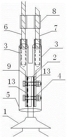
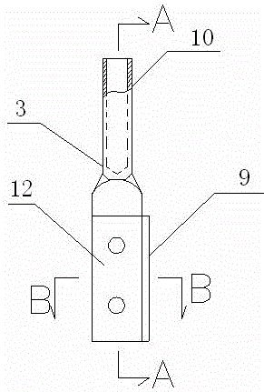
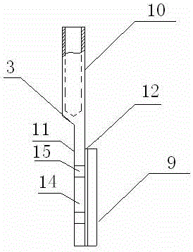
[0044] Example 1: Reference Figure 1-7 . A device for preventing heating of 110kV outdoor fully prefabricated dry-type cable terminals in this embodiment includes 110kV outdoor fully prefabricated dry-type cable terminals 1, copper terminals 2, copper-aluminum transition equipment clamps 3, fasteners 4, points Fork-type heat shrinkable tube 5, wire jumper Ⅰ6, wire jumper Ⅱ7, amp clamp 8, copper wing plate 9, crimping tube 10, copper-aluminum transition plate 11, copper surface layer 12, calendered copper foil 13, aluminum Base plate 14 , through hole 15 , vertical sleeve 16 , vertical branch sleeve 17 .
[0045] Installation and connection relationship: two copper-aluminum transition equipment clamps 3 are respectively installed on both sides of the copper terminal 2, and the copper-aluminum transition equipment clamp 3 includes a crimping tube 10 for installing wire jumpers and is located under the crimping tube 10 The copper-aluminum transition plate 11, the copper-alumin...
Embodiment 2
[0047] For the installation method of a device for preventing heating of 110kV outdoor fully prefabricated dry-type cable terminals in this embodiment, refer to the attached Figure 1-7 , when installing, first put the vertical branch sleeve 17 of the bifurcated heat shrinkable tube 5 on the two copper-aluminum transition equipment clips 3 with copper wings 9 and the wire jumper I6 and wire jumper II7; secondly , the copper wing plates 9 of the two copper-aluminum transition equipment clamps 3 are respectively located and close to the two sides of the copper terminal 2, between the copper terminal 2 and the copper surface layer 12 of the copper-aluminum transition equipment clamp 3 Pad the rolled copper foil 13, and then use the fastener 4 to fasten the copper terminal 2, the rolled copper foil 13 and the copper-aluminum transition equipment clamp 3 with the copper wing plate 9; again, heat the bifurcated heat-shrinkable tube 5, Sequentially shrink and seal the copper terminal...
PUM
 Abstract
Description
Claims
Application Information
 - Generate Ideas
- Intellectual Property
- Life Sciences
- Materials
- Tech Scout
- Unparalleled Data Quality
- Higher Quality Content
- 60% Fewer Hallucinations
Browse by: Latest US Patents, China's latest patents, Technical Efficacy Thesaurus, Application Domain, Technology Topic, Popular Technical Reports.
© 2025 PatSnap. All rights reserved.Legal|Privacy policy|Modern Slavery Act Transparency Statement|Sitemap|About US| Contact US: help@patsnap.com


