
Rail conveyor system

A conveyor and track technology, applied in the field of rail conveyor systems, can solve problems such as large rolling resistance

Active Publication Date: 2013-05-08
NEWCASTE INNOVATION LTD
View PDF4 Cites 18 Cited by
  • Summary
  • Abstract
  • Description
  • Claims
  • Application Information

AI Technical Summary

Problems solved by technology

However, belt conveyors have greater rolling resistance than trucks and railroads due to the inherent motion losses of transportation
These losses effectively limit the operating length of conventional belt conveyors

Method used


Image

  • Rail conveyor system
  • Rail conveyor system
  • Rail conveyor system

Examples


Embodiment Construction

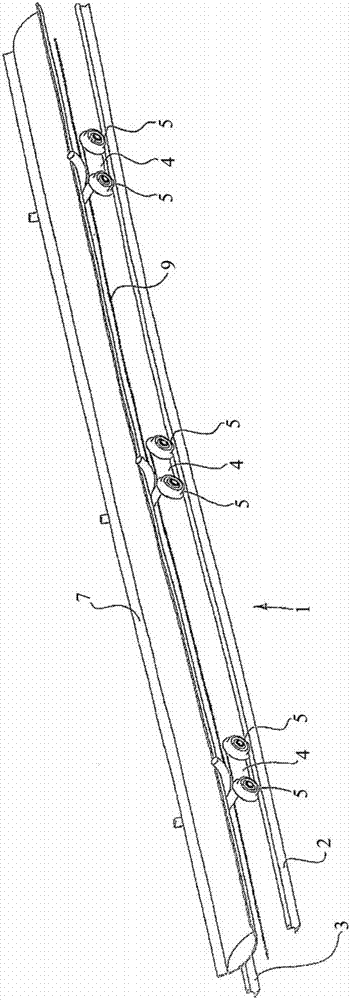
[0045] In a preferred form of the invention the rail conveyor system is formed by providing a track 1 which generally comprises two conventional rails 2 and 3 side by side. These rails may be similar to those used in conventional train tracks and may either be mounted on sleepers above ground as in conventional rail systems, or elevated or supported on rails as is known from typical belt conveyor systems. on the frame.

[0046] The system also includes a plurality of spaced apart carriages 4 running on wheels 5 supported by rails 2 and 3 .

[0047] exist figure 2 As can be seen more clearly in , the wheels generally have flanges, seen at 6, and engage the inner edges of rails 2 and 3 in a manner similar to conventional train systems.

[0048] The rail conveyor system according to the invention also comprises a continuous conveyor belt 7 supported by supports 4 and conveyed generally in suitably shaped yolks 8 mounted on each support.

[0049] In a preferred form of the inv...


PUM


Abstract

A rail conveyor system combining the low friction attributes of railway transportation with the continuous bulk handling advantages of belt conveyors, uses a multiplicity of spaced carriages (4) running on steel wheels (5) on rail tracks (2, 3) to support a continuous carry belt (7). The system is driven by various means including a rope (9) extending between the carriages. Various other drive means including drive belt technology are also described along with loading and unloading stations and distributed drive stations.

Description

technical field [0001] The present invention relates to rail conveyor systems designed especially, but not exclusively, for transporting bulk materials over distances of about 10 km to 100 km. Background technique [0002] In the past, belt conveyors were often used to transport large quantities of material over distances of up to 20 kilometers. These bulk materials typically include coal, iron ore, bauxite, and the like. Depending on operational requirements, transport distances vary widely, but currently most of these bulk materials are transported tens or even hundreds of kilometers to a processing plant, power station or export terminal. The choice of bulk material handling system depends on haul distance, production volume, and terrain, and in most cases will rely on belt conveyors, as well as haul trucks and / or rail systems. [0003] The need to increase fuel prices and reduce greenhouse gas emissions, as well as the growing demand for minerals, has put considerable ...

Claims


Application Information

Patent Timeline
Patent Type & Authority Applications(China)
IPC IPC(8): E01B25/10B65G15/08B65G53/00B61D11/00B65G35/00E21F13/08
CPCB65G17/02B61B9/00B65G21/22B65G39/20B61D11/02B61B13/04E21F13/083Y02T30/00
Inventor 克雷格·安东尼·维勒
Owner NEWCASTE INNOVATION LTD
Learn More