
Replaceable limiting and locking damping energy consumption device

An energy-consuming device and position-limiting technology, which is applied to bridge parts, bridges, buildings, etc., can solve problems such as beam damage, unreduced bridge damage, beam cracking, etc., and achieve reduced deformation of the main structure, good seismic effect, The effect of preventing falling beams

Inactive Publication Date: 2013-05-08
北京城安建设工程检测有限公司
View PDF4 Cites 9 Cited by
  • Summary
  • Abstract
  • Description
  • Claims
  • Application Information

AI Technical Summary

Problems solved by technology

[0003] The current anti-seismic energy-dissipating dampers for bridges are usually fixedly connected directly to the pier beam, which not only changes the stress of the simple beam bridge and continuous beam bridge system, but also prevents the longitudinal deformation of the beam from being released, resulting in cracking of the beam body, and is inconvenient for damping The repair and maintenance of the device, the traditional damper is easily damaged under the action of an earthquake and usually cannot be reused, which will increase the maintenance cost of the bridge
The traditional structural measure to prevent falling beams is to set limit stops on bridge piers. Although it plays a role in preventing beams falling, this measure does not reduce the damage to bridges caused by earthquake energy.
At the same time, under the action of the earthquake, the beam body is very easy to collide with the block, causing the beam body to be damaged, which brings inconvenience to the post-disaster reconstruction.
At present, there is no multiple anti-seismic energy consumption device that can effectively prevent falling beams

Method used


Image

  • Replaceable limiting and locking damping energy consumption device
  • Replaceable limiting and locking damping energy consumption device
  • Replaceable limiting and locking damping energy consumption device

Examples


Embodiment Construction

[0030] Specific embodiments of the present invention will be described in detail below in conjunction with the accompanying drawings.

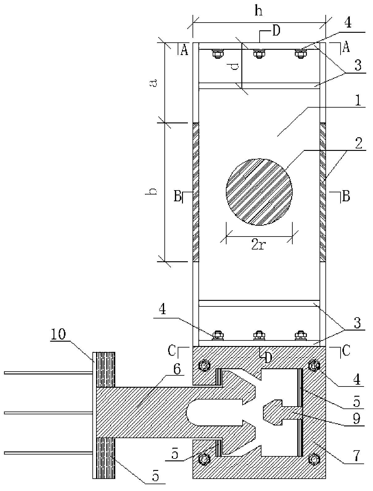
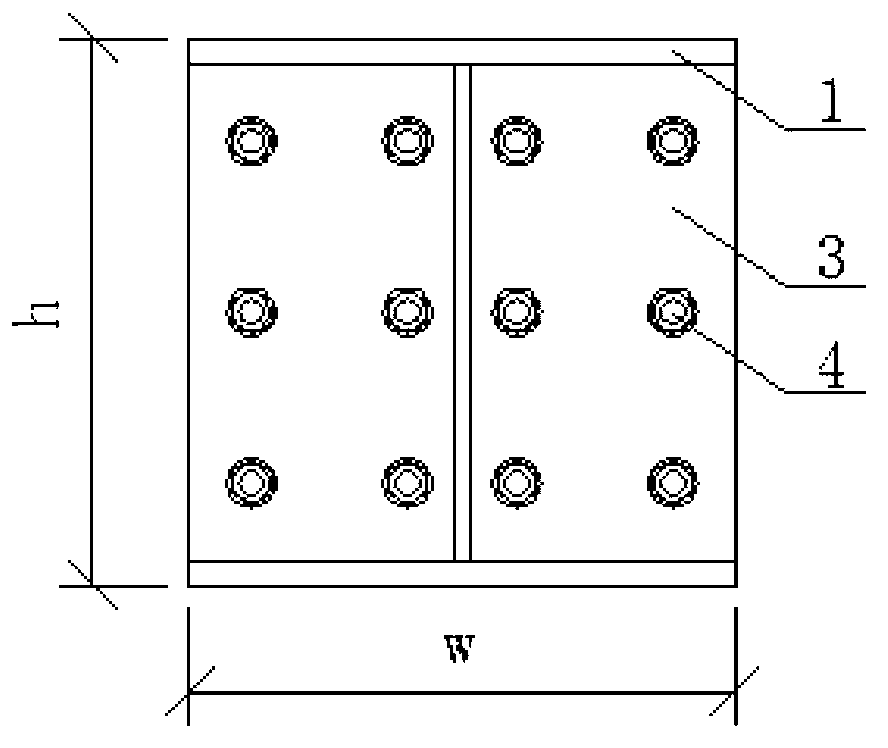
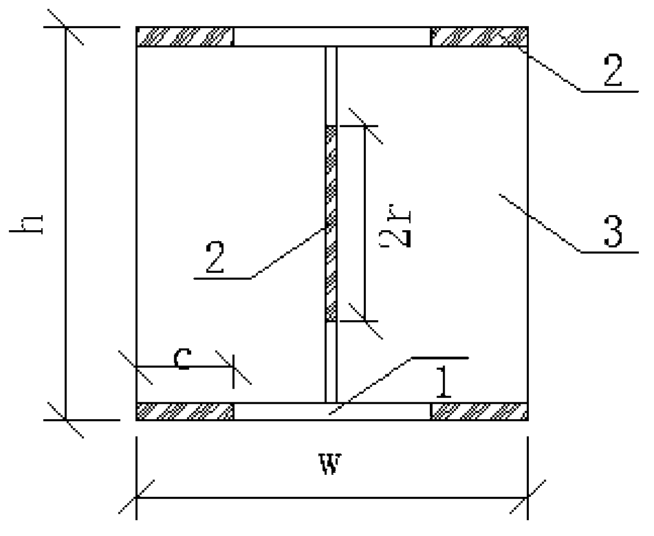
[0031] Such as Figure 1 to Figure 6Shown is the structural diagram of the present invention, the replaceable position-limiting locking shock-absorbing energy-dissipating device includes welded I-beam 1, metal composite material energy-dissipating plate 2, transverse diaphragm 3, high-strength bolts 4, and rubber protection pad 5 , self-locking snap plate 6, slot box 7, slot box cover plate 8, interlocking snap plate 9, embedded steel plate 10; the web and flange of welded I-beam 1 are cut and replaced with metal composite energy consumption The two ends of the welded I-beam 1 are respectively connected with two transverse diaphragms 3 placed at intervals, and the outermost transverse diaphragm 3 at one end is connected with a draw-in box 7, and one side of the draw-in box 7 A protruding interlocking buckle plate 9 is provided on the wall, an...


PUM


Abstract

The invention discloses a replaceable limiting and locking damping energy consumption device and belongs to the field of civil engineering and mechanical engineering. A web plate and flanges of welding joint steel (1) are cut to be replaced with metal compound energy consumption plates (2); two ends of the welding joint steel (1) are connected with horizontal partition plates (3), and the partition plate at one end is connected with a clamping slot box (7); the side wall of one side of the clamping slot box (7) is provided with a protruded interlocking clamping plate (9); a side wall which is opposite to the side wall provided with the interlocking clamping plate (9) is provided with a slot which extends into a self-locking clamping plate (6); the self-locking clamping plate (6) is a steel plate of which the end is gradually protruded and the middle is provided with an opening; and the opening of the self-locking clamping plate (6) is opposite to a bulge of the interlocking clamping plate (9). In earthquake, after the structural deformation exceeds an expected value, a bridge pier and a beam body are locked, and the connection mode is changed by a self-locking device, the deformation of a main body structure is reduced, and the condition that a beam of a bridge falls and the bridge is damaged can be avoided; and the replaceable limiting and locking damping energy consumption device is simple in structure, can effectively prevent the beam from falling off and has good energy consumption capacity.

Description

technical field [0001] The invention belongs to the field of anti-seismic and shock-absorbing technology of bridge engineering, and relates to a kind of original steel material that weakens the flange and web of the I-beam and replaces it with a metal composite energy-dissipating plate, and at the same time, the end of the I-beam is connected with a self-locking device , so as to form a replaceable limit locking shock absorbing energy dissipation device under earthquake action. The invention has the advantages of low cost, outstanding seismic performance, effective prevention of falling beams, convenient construction and good development prospect. Background technique [0002] In the 2008 Wenchuan earthquake and the 2011 Japanese earthquake, hundreds of girder bridges were damaged by falling beams in the earthquake, and the road and bridge projects, which were the lifeline projects for post-disaster rescue, were severely damaged, making it impossible for rescuers to reach th...

Claims


Application Information

Patent Timeline
Patent Type & Authority Applications(China)
IPC IPC(8): E01D19/00
Inventor 闫维明石鲁宁何浩祥马裕超
Owner 北京城安建设工程检测有限公司
Learn More